//Sample code for
//DS1307 RTC Ineterfacing with PIC16F877A
//Coded by Pynn Pynn
//Compiler: mikroC 8.0.0
//http://picnote.blogspot.com
//07/06/2008
//Use with your own risk
unsigned short read_ds1307(unsigned short address );
unsigned short sec;
unsigned short minute;
unsigned short hour;
unsigned short day;
unsigned short date;
unsigned short month;
unsigned short year;
unsigned short data;
char time[9];
char ddate[11];
unsigned char BCD2UpperCh(unsigned char bcd);
unsigned char BCD2LowerCh(unsigned char bcd);
void main(){
I2C_Init(100000); //DS1307 I2C is running at 100KHz
PORTB = 0;
TRISB = 0; // Configure PORTB as output
TRISC = 0xFF;
Lcd_Init(&PORTB); // Initialize LCD connected to PORTB
Lcd_Cmd(Lcd_CLEAR); // Clear display
Lcd_Cmd(Lcd_CURSOR_OFF); // Turn cursor off
Lcd_Out(1, 1, "TIME:");
Lcd_Out(2, 1, "DATE:");
while(1)
{
sec=read_ds1307(0); // read second
minute=read_ds1307(1); // read minute
hour=read_ds1307(2); // read hour
day=read_ds1307(3); // read day
date=read_ds1307(4); // read date
month=read_ds1307(5); // read month
year=read_ds1307(6); // read year
time[0] = BCD2UpperCh(hour);
time[1] = BCD2LowerCh(hour);
time[2] = ':';
time[3] = BCD2UpperCh(minute);
time[4] = BCD2LowerCh(minute);
time[5] = ':';
time[6] = BCD2UpperCh(sec);
time[7] = BCD2LowerCh(sec);
time[8] = '\0';
ddate[0] = BCD2UpperCh(date);
ddate[1] = BCD2LowerCh(date);
ddate[2] ='/';
ddate[3] = BCD2UpperCh(month);
ddate[4] = BCD2LowerCh(month);
ddate[5] ='/';
ddate[6] = '2';
ddate[7] = '0';
ddate[8] = BCD2UpperCh(year);
ddate[9] = BCD2LowerCh(year);
ddate[10] = '\0';
Lcd_Out(1,6,time);
Lcd_Out(2,6,ddate);
Delay_ms(500);
}
}
unsigned short read_ds1307(unsigned short address)
{
I2C_Start();
I2C_Wr(0xd0); //address 0x68 followed by direction bit (0 for write, 1 for read) 0x68 followed by 0 --> 0xD0
I2C_Wr(address);
I2C_Repeated_Start();
I2C_Wr(0xd1); //0x68 followed by 1 --> 0xD1
data=I2C_Rd(0);
I2C_Stop();
return(data);
}
unsigned char BCD2UpperCh(unsigned char bcd)
{
return ((bcd >> 4) + '0');
}
unsigned char BCD2LowerCh(unsigned char bcd)
{
return ((bcd & 0x0F) + '0');
}
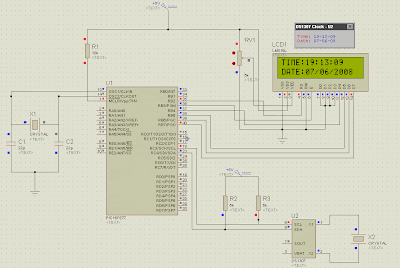
As I don't have DS1307 in hand, so I test my code with Proteus ISIS simulator. The image shows the working clock. Click on the image for big image.


16 comments:
thanks for sharing the code.
may i know how to set the time??
Please check out my post about this at http://picnote.blogspot.com/2008/08/ds1307-setting-time.html
i have build up everything exactly same with yours, but my LCD screen just show out
time : =1:=1:=1
date : =1/=1/20=1
, without counting also.
no matter how i try, it still same.can u give me some guide?
Hello, ah_bear
This code is for reading time from the DS1307 so you have to write some values to DS1307 before you can read them. Please see http://picnote.blogspot.com/2008/08/ds1307-setting-time.html for writing values to the DS1307.
Just put the code for setting time before the while(1) loop.
My LCD Clock with DS1307 is now running just fine.
ah_bear, I have posted the detail about my answer at http://picnote.blogspot.com/2009/01/simple-clock-using-ds1307-pic16f877a.html . Please take a look.
Punkky
Have you come across a code/schematic that uses a ds1307 that can count down to a set date/time? I'd like to see if I can make a DDD:HH:MM count down timer. Set the current date/time, set the target date/time and it displays the time remaining in a count down
Can anyone share PIC 16F877A interface to GSM Modem
hi benik .. any luck .. ??
hi Mr. Punkky..congratulation..i already see your blog and its amazing me.look u are really expert with PIC.here i would like to have some help from u. i used five 7-,pic16f877a and bcd(binary code decimal) ic with 3 input switch of push button. the first input,when switch 1 is push, then then display will display A0000-A3333, switch 2 B3334-B6666 and switch 3 C6667-C9999. the counter will only count up when switch is push. lets says, present display is A2333, when push button 1 is pushed,it will count up to A2334. the scope of display may can be reduced to A000-A333 or A00-A33..thanks..i really hope that u can give solution to this problems.
i have the simulation circuit in proteus7.2 and us CCS C compiler and C language program coding but failed to get result..
What is the Value of the crystal attached to the DS1307? is it 32.7...kHz or?
PLEASE MY FRIENDS I REQUEST YOU PEOPLE TO SEND ME MULTISIM COMPONENT OF DS1307... SO THAT I CAN ALSO BUILD A DIGITAL CLOCK FOR MY PROJECT IN MY ACADEMIC.... PLEASE SEND MULTISIM COMPONENT OF DS1307 TO anand1586@yahoo.com.....please i request you friends.......
thank you....
what MHz crystal are you using for DS1307???I am using 32.78 crystal...but the clock s running 35 minutes faster than normal time....
I like your clock project very much. Btw, may I know what crystal are you using for that microcontroller? (Of course, it's understood that the DS1307's using a 32.768kHz crystal)
Also, the "delay_ms(500)" in the infinite while loop caused the LCD to skip a few seconds periodically. I'm not sure why it happened on the microcontroller with 10MHz crystal. The nearest solution for me to prevent this from happening is decreasing the delay_ms to at least 50. :D
If the crystal's speed is like 20MHz, I guess one can allow much more time for the HD44780 display to refresh itself. :D
please i have a problem hear im not searching to have the time ot the date ,i have to find how can i see in the lcdwhat i write in my pc
i know that i must add a connector db9 and an RS232 but i can't resolve the program
thanks
i want 7segment countdown timer with overflow mode pls help
Post a Comment