Showing posts with label Clock. Show all posts

Friday, May 21, 2010

DIY LED Watch vs Panerai PAM 127

I have completed a prototype of my LED Watch. I will post the detail about how to make it later. The watch case and strap are missing :)
Features:
- Programmable (via ICSP)
- Vintage 7-segment LEDs with slim sigments
- Powered from a coin cell 3.7V Li-ion rechargeable battery
- Built-in USB battery charger

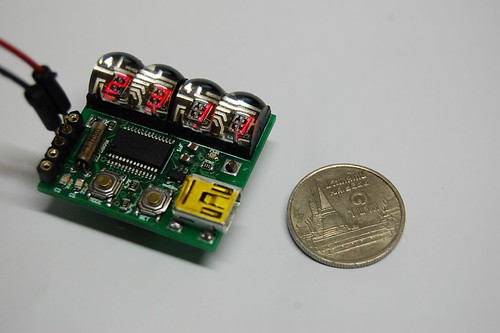
Size comparison between the DIY LED Watch size and a 1 Thai Baht coin.


On my wrist with help of transparent tape :).
DIY Led Watch

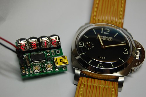
The LED Watch prototype is on the left. Panerai PAM 127 or the "Fiddy" is on the right. In case that you are wondering about the strap, it is custom made from a Louis Vuitton bag.
DIY LED Watch, Panerai PAM127

Please comeback and check out for the making of DIY LED Watch later.

Tuesday, April 14, 2009

Classic LED 7-Segment Displays

Just recently I have been addicted to old LED displays as they are small and bright and I love the classic look. We can see them in vintage calculators and vintage led watches. However these displays consume significant amount of power, so they are not used in watches and calculators anymore. As they are replaced by LCD, these LED 7-Segment displays are not in production anymore and difficult to obtain.

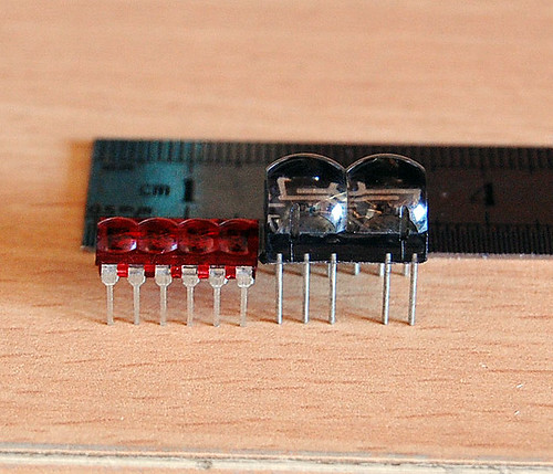
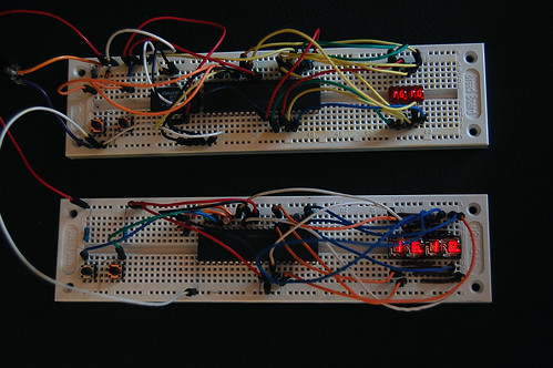
Now, I have 2 models of the classic LED 7-Segment as shown in the picture below: HP 5082-7414 from HP is on the left. It’s a 4-digit Red LED 7-Segment very nice for wristwatch. The one on the right is an 2-digit Red LED 7-Segment from an unknown maker. It can be used in a wristwatch too (with a little bit bigger case).

LED 7-Segment Display HP 5082-7414

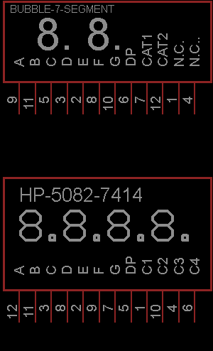
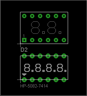
Based on my inspection, I have made symbols for these displays with Eagle 5.4.0 free version. The displays are common cathode and the symbols are below

LED 7-Segment Display HP 5082-7414 schematic

The PCB footprints are as the following (DIP 12)

LED 7-Segment Display HP 5082-7414 PCB footprint

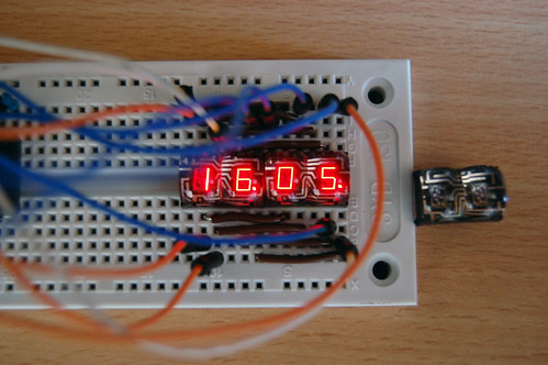
I have made simple clocks using these displays and PIC16F887. The real thing looks much better than the photo. The displays are bright red and sun light viewable. Very COOL!!! They are on my computer desk and I love to see them very often.
bubble-7-segment-clock

LED 7-Segment Display HP 5082-7414 clock

LED 7-Segment Display HP 5082-7414 digital clock

Each clock consumes about 0.25W (50mA, 5V) when the PIC16F887 operates at 250kHz (display refresh rate is about 61Hz). The amount of consumed current can be reduced significantly if I use some current limit resistors. But the displays will be dimmer than without resistors. I will try to use PWM for reducing the power consumption as I don’t want to put 8 resistors into my design. The schematic/PCB and firmware including source code in MikroC will be made public once I have complete all of the designs. I will even have kits for sell if my time permitted.

Friday, February 20, 2009

1Hz Clock Generator using PIC12F675

Based on the idea from http://www.josepino.com/pic_projects/?timebaseI have created a 1Hz Clock Generator. I use PIC12F675 as it's available locally. Its price is just about US$1.
The concept is using 32.768kHz crystal as a clock for the PIC. Therefor, the internal instruction clock is 32768/4 = 8192 Hz. By using the 16 bit Timer1 to count the instruction clock cycles, the interrupt will occur every 8 second. This period can be reduced by setting initial value of the Timer1 (TMR1H:TMR1L). I have to make Timer1 to count up to 8192 for generating overflow interrupt every 1 second. To make Timer1 count up to 8192, the initial value of TMR1 must be 65536-8192 = 57344 or 0xE000. This means TMR1H = 0xE0 and TMR1L = 0x00. In this case, I need to set only the TMR1H=0xE0 and let TMR1L runs continuously. By changing the initial value of Timer1, I can generate almost any frequencies.

An application for this project is a precise 1Hz blinking LED signal :) ha ha. I know that it's not useful but I think it's fun to look at (am I crazy?). Another application is a precise 1Hz time base for a clock.

The source code is written in MikroC.

// PIC12F675
// 1Hz Time Base Osc.
// Timer1 Module
// 32.768 KHz
unsigned short tick;
void Init ();
void interrupt ()
{
        if (PIR1.TMR1IF)
        {
                TMR1H = 0xE0;
                PIR1.TMR1IF = 0;
                tick = 1;
        }
}
void main ()
{
        tick = 0;
        //Initialize Ports and Timer1 Module
        Init ();
        while (1)
        {
                if (tick)
                {
                        tick = 0;
                        GPIO = (1 << 2);
                }
                if (TMR1H > 0xF0)
                {
                        GPIO = 0;
                }
        }
}
void Init ()
{
        TRISIO = 0;
        //Make all pins as output ports
        GPIO = 0;
        //Use Timer1 module
        INTCON.GIE = 1;
        INTCON.PEIE = 1;
        T1CON = 0x01;
        //Overflow every 8192
        TMR1H = 0xE0;
        TMR1L = 0x00;
        //  Enable TMR1 interrupt
        PIE1.TMR1IE = 1;
}


The schematic is as the following image.
1Hz Clock generator using PIC12F675


The PCB:


3D version:

Monday, January 5, 2009

A Simple Clock using DS1307 + PIC16F877A

Even I have posted about "DS1307 + PIC16F877A", I didn't have chance to make a real prototype of the clock. I have done only on the simulation software. Today, I have received a comment about that post. ah_bear followed my code and schematic on that post but the clock didn't work. This is because the code on that post is for reading time from DS1307 so there must be some values in the DS1307 before you can read. The solution is simple. Just place setting time codes before reading codes.

This time, I have made a real prototype to confirm that it's working. There is no setting buttons. If you want to make a real usable clock you have to implement the button interfaces (I may make one and post it here). The photo of my working prototype is featured below. Please check out my flikr at http://flickr.com/photos/punkky/ for more photos.
A simple clock using DS1307 and PIC16F877A
The schematic of the clock is very simple. Please note that the schematic does not show power supply to the PIC16F877A and the DS1307, you have to connect them by youself. If you are new to PIC/LCD interface please see MikroC "Hello World!" LCD example .
Schematic of a simple clock using DS1307 and PIC16F877A

The source code:
//Sample code for
//DS1307 RTC Interfacing with PIC16F877A
//Coded by punkky@gmail.com
//Compiler: mikroC 8.0.0
//http://picnote.blogspot.com
//05/01/2009
//Use with your own risk

unsigned short read_ds1307(unsigned short address );
void write_ds1307(unsigned short address,unsigned short w_data);
unsigned short sec;
unsigned short minute;
unsigned short hour;
unsigned short day;
unsigned short date;
unsigned short month;
unsigned short year;
unsigned short data;
char time[9];
char ddate[11];

unsigned char BCD2UpperCh(unsigned char bcd);
unsigned char BCD2LowerCh(unsigned char bcd);

void main(){

I2C_Init(100000); //DS1307 I2C is running at 100KHz
PORTB = 0;
TRISB = 0// Configure PORTB as output
TRISC = 0xFF;
Lcd_Init(&PORTB); // Initialize LCD connected to PORTB
Lcd_Cmd(Lcd_CLEAR); // Clear display
Lcd_Cmd(Lcd_CURSOR_OFF); // Turn cursor off
Lcd_Out(11"TIME:");
Lcd_Out(21"DATE:");

//Set Time
write_ds1307(0,0x80); //Reset second to 0 sec. and stop Oscillator
write_ds1307(1,0x10); //write min 27
write_ds1307(2,0x01); //write hour 14
write_ds1307(3,0x02); //write day of week 2:Monday
write_ds1307(4,0x05); // write date 17
write_ds1307(5,0x01); // write month 6 June
write_ds1307(6,0x09); // write year 8 --> 2008
write_ds1307(7,0x10); //SQWE output at 1 Hz
write_ds1307(0,0x00); //Reset second to 0 sec. and start Oscillator

while(1)
{
sec=read_ds1307(0); // read second
minute=read_ds1307(1); // read minute
hour=read_ds1307(2); // read hour
day=read_ds1307(3); // read day
date=read_ds1307(4); // read date
month=read_ds1307(5); // read month
year=read_ds1307(6); // read year

time[0] = BCD2UpperCh(hour);
time[1] = BCD2LowerCh(hour);
time[2] = ':';
time[3] = BCD2UpperCh(minute);
time[4] = BCD2LowerCh(minute);
time[5] = ':';
time[6] = BCD2UpperCh(sec);
time[7] = BCD2LowerCh(sec);
time[8] = '\0';

ddate[0] = BCD2UpperCh(date);
ddate[1] = BCD2LowerCh(date);
ddate[2] ='/';
ddate[3] = BCD2UpperCh(month);
ddate[4] = BCD2LowerCh(month);
ddate[5] ='/';
ddate[6] = '2';
ddate[7] = '0';
ddate[8] = BCD2UpperCh(year);
ddate[9] = BCD2LowerCh(year);
ddate[10] = '\0';

Lcd_Out(1,6,time);
Lcd_Out(2,6,ddate);
Delay_ms(50);
}
}

unsigned short read_ds1307(unsigned short address)
{
I2C_Start();
I2C_Wr(0xd0); //address 0x68 followed by direction bit (0 for write, 1 for read) 0x68 followed by 0 --> 0xD0
I2C_Wr(address);
I2C_Repeated_Start();
I2C_Wr(0xd1); //0x68 followed by 1 --> 0xD1
data=I2C_Rd(0);
I2C_Stop();
return(data);
}

unsigned char BCD2UpperCh(unsigned char bcd)
{
return ((bcd >> 4) + '0');
}

unsigned char BCD2LowerCh(unsigned char bcd)
{
return ((bcd & 0x0F) + '0');
}
void write_ds1307(unsigned short address,unsigned short w_data)
{
I2C_Start(); // issue I2C start signal
//address 0x68 followed by direction bit (0 for write, 1 for read) 0x68 followed by 0 --> 0xD0
I2C_Wr(0xD0); // send byte via I2C (device address + W)
I2C_Wr(address); // send byte (address of DS1307 location)
I2C_Wr(w_data); // send data (data to be written)
I2C_Stop(); // issue I2C stop signal
}

Saturday, December 20, 2008

Frequency Divider

I am always looking for perfect frequency oscillator for a given budget for my clock projects. Searching on eBay provided a lot of good frequency oscillators including OCXO (Oven Controlled Crystal Oscillator) and Rubidium Frequency Oscillator. Most of them are for telecommunication systems and audio systems. But, I want to use the oscillator just for making a good clock. Yes, just a real clock for telling time.Those oscillators on eBay provide frequencies that not suitable for making a clock. For example, 10MHz,11.2896, MHz, 16.9344MHz etc.,

There are some techniques to make use of these oscillators in clock projects. I have post a solution for 11.2896MHz in "Using 11.2896 MHz with TMR1 (timer1 module)".

For 10MHz oscillator, I will use ripple counters as the frequency divider to divide the 10MHz to lower frequency and use it as a time reference for my clocks. I got information about 10MHz frequency division from Seiichi Inoue's website. From the web, 10MHz frequency can be divided by using 3 pcs. of Dual Decade Counter (74390 or 74HC390). By using the schematic below, I can get 100Hz from 10MHz input. By feeding 100Hz to PIC Microcontroller with appropriate firmware I will get a good accuracy clock.
10MHz Frequency DividerIt's not so easy to divide 16.9344MHz to appropriate frequency for my clocks. However, I will try to figure it out and post it here.

Saturday, December 6, 2008

Digital Clock without Microcontroller

Digital Clock Big Digit I have found a digital clock that uses just a clock chip without microcontroller from Electronickits.com . The picture above is the Digital Clock With 24 Hour Timer made by Canakit.com . It uses LM8560 clock chip which incorporates a wide range of features such as alarm, snooze, and 24 hour timer. The digit height is 50mm and made of 87 discrete LEDs. It can be a unique wall clock by just cover the digits with red Plexiglas and hang it on the wall.

Saturday, November 22, 2008

Small Nixie Tube

I have a plan to build a Nixie Clock so I search for its information and blog it here for further reference.

IN-16 may be not the smallest nixie tube but it's small enough to make a nice desk top nixie clock. The character height is about 13mm. I will use IN-16 for my upcoming nixie clock. There are some nixie clock kits that use IN-16 nixie tube so I am thinking about buying a kit or building it from scratch.

Wednesday, November 19, 2008

PCB for 7-Segment PIC Digital Clock

I have designed a single-sided PCB for the PIC Digital Clock. Because the autorouter is not good for routing single-sided PCB so I have to route by hand. It was my first hand routed PCB design and it was a time consuming task. I haven't tested the PCB yet. Use it by your own risk. I will produce this PCB and test it later.

As I don't have server to upload the Eagle file, please contact me if you want the file or PDF version of the image below.

PCB for 7-Segment PIC Digital Clock

Components side of the PCB. The red lines are jumpers.
Component placement on the PCB of 7-Segment PIC Digital Clock

Sunday, November 16, 2008

7-Segment PIC Digital Clock : The photographs

The prototype of the 7-Segment PIC Digital Clock. Check out 7-Segment Digital Clock for the schematic and source code.
7-Segment Digital Clock
7-Segment Digital Clock PIC Microcontroller
7-Segment Digital Clock PIC16F627A
7-Segment Digital Clock PIC16F628

Saturday, November 15, 2008

Using 11.2896 MHz with TMR1 (timer1 module)

11.2896 MHz Rubidium Frequency Standard

A precision clock is my ultimate goal of making clocks. I know that cesium oscillator is to most precise clock on earth. However, a cesium clock is too expensive to play with. My option is using Rubidium oscillator which is the second most accurate oscillator after the cesium (I don't have reference about this) and its cost is more accessible. Searching on eBay about Rubidium Frequency Oscillator brought me to Ultra low jitter 11.2896Mhz Rubidium Frequency Clock . I am thinking about buying this item.
The question is 'How to make use of 11.2896 MHz frequency oscillator with my clock?'. If I run my MCU with this frequency, the internal frequency will be 11.2896MHz/4 = 2.8224 MHz. How to use this frequency to drive timer1 module for making a precision clock? TMR1 is a 16bit timer so it can count from 0 to 65535 before overflow. If I use TMR1 with this frequency without any setting, the TMR1 will send interrupt 2822400/65536= 43.06640625Hz or every 0.023219955 second which is unusable.
I have to find the initial value of the TMR1 for the best precision . The conditions are
1. The number of interrupts per second must be integer so I can count it precis
2. The initial value must be in form 0x##00. That means I have to set only the first 2 bits of TMR1 (TMR1H) as setting the lower bits takes some time and effects the clock precision.

The Solution
Expanding 2822400 results
2822400 = 256 x 49 x 25 x 9 = 57600 x 49
The meaning
If I set TMR1 to count upto 57600, it will send interrupt 49 times/second. Wow! It meets my first condition. To set TMR1 to count up to 57600, I have to set the initial value of TMR1 to 65536-57600 = 7936 = 0x1F00. Wow again!! It meets the second condition.

Now, I have to set TMR1H = 0x1F and count the number of interrupts to 49 to get 1 second time interval. Just perfect!

Thursday, November 13, 2008

Making a Digital Clock (Updated)

My fist Microcontroller project, PIC Digital Clock, is shown below.
Prototype digital clock on Breadbord

I have added time setting feature to make it to be a usable clock. The updated version is shown below:
7-Segment Digital Clock

More features will be added in the future.
There is no fast or slow time setting as in normal/simple digital clocks. In this clock, each digit of the clock display can be set one by one via 2 setting buttons.
Features
1. Bright Led 7-Segment display without Multiplexing
2. Display: Hour, Minute, Second
3. Set time via 2 buttons
4. Set time Digit by Digit
5. Use internal oscillator of PIC16F627a or PIC16F628
6. Use 32.768KHz crystal for better clock accuracy


Setting Time:
1. The clock shows 12:34:56 when power the clock on. The first digit of hour (it's number 1 in this case) will be blinking to notify that the time is not correct and need to be set.
2. Press SET button to count up the digit.
3. Press MODE button when the digit is the correct time. The next digit will be blinking.
4. Repeat step 2 and 3 for setting minute and second.
5. Make sure that pressing MODE button for setting the second digit of second at the correct time.


Shecmatic of the Digital Clock
Schematic of a Digital Clock using PIC16F627a or PIC16F628 and Led 7-Segment with showing second

Example of a PCB design of the Digital Clock
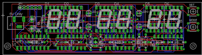
PCB of a Digital Clock using PIC16F627a or PIC16F628 and Led 7-Segment with showing second

The firmware ( source code in C ) written in MikroC
//6 digit  clock
//Using timer1 16bit counter interrupt
// PIC16F627A or PIC16F628
// Internal Clock 4MHz
// PUNKKY@gmail.com
#define MODE PORTB.F4
#define SET PORTB.F5
#define Sec_port_l PORTA.F6
#define Sec_port_h PORTA.F4
#define Min_port_l PORTA.F3
#define Min_port_h PORTA.F2
#define Hr_port_l PORTA.F1
#define Hr_port_h PORTA.F0
#define Blink PORTA.F7
#define HTMR1 0x80
#define LTMR1 0x00
typedef unsigned short uns8;
uns8 i;
uns8 hr_h;
uns8 hr_l;
uns8 min_h;
uns8 min_l;
uns8 sec_h;
uns8 sec_l;
uns8 tick;
uns8 myTimer;
uns8 setting_time;
void setup ();
void set_time ();
void show_time ();
void display (uns8 digit);
void blink_digit (uns8 digit);
void check_bt ();

//void check_bt(); //chech button
void interrupt ()
{
        PIR1.TMR1IF = 0;
        // clears TMR1IF
        TMR1H = HTMR1;
        tick = 1;
        Blink = 1;
        sec_l ++;
        if(sec_l>9){
            sec_l = 0;
            sec_h++;
        }
        if(sec_h>5){
            sec_h=0;
            min_l++;
        }
        if(min_l>9){
            min_l = 0;
            min_h++;
        }
        if(min_h>5){
            min_h = 0;
            hr_l++;
        }
        if(hr_l>9){
            hr_l = 0;
            hr_h++;
        }
        if(hr_h >2){
            hr_h = 0;
        }
        if(hr_h >=2 && hr_l>3){
           hr_h = 0;
           hr_l = 0;
        }
}
void main ()
{
        setup ();
        
        //Set time
        hr_h = 1;
        hr_l = 2;
        min_h = 3;
        min_l = 4;
        sec_h = 5;
        sec_l = 6;
        show_time ();
        setting_time = 1;
        set_time();
        while (1)
        {
                //blink_digit();
                if (tick)
                {
                        tick = 0;
                        show_time ();
                        Delay_ms (300);
                        Blink = 0;
                }
                check_bt ();
        }
}
void setup ()
{
        tick = 0;
//Digital output on PORTA
        CMCON = 0x07;
        //Input buttons + external clock
        TRISB = 0xB0;

        PORTB = 0x00;
        TRISA = 0x00;
        PORTA = 0x00;
        //Internal Clock 4MHz
        PCON.OSCF = 1;
        // Prescaler 1:1   external clock
        T1CON = 0x0F;

        PIE1.TMR1IE = 0;  // disable interupt to stop the clock

        INTCON = 0xC0;
        // Set GIE, PEIE
        TMR1L = LTMR1;
        TMR1H = HTMR1;
        // TMR1 starts at 0x0BDC = 3036 to make TMR1 counts to 62500 and
        // overclows in every 0.1 sec
        // Math: 1/500000*8*62500 = 0.1
        // 1/5000000 : time for 20MHz crystal (internal clock will be 20/4 = 5MHz)
        // 8: prescaler
        // 62500: TMR1 counts to 62500
        // Counting number of overflows to 10 will get 1 sec.

}

void show_time ()
{
        display (1);
        display (2);
        display (3);
        display (4);
        display (5);
        display (6);
}
void display (uns8 digit)
{
        switch (digit)
        {
                case 1 :
                PORTB = hr_h;
                Hr_port_h = 1;
                Hr_port_h = 0;
                break;
                case 2 :
                PORTB = hr_l;
                Hr_port_l = 1;
                Hr_port_l = 0;
                break;
                case 3 :
                PORTB = min_h;
                Min_port_h = 1;
                Min_port_h = 0;
                break;
                case 4 :
                PORTB = min_l;
                Min_port_l = 1;
                Min_port_l = 0;
                break;
                case 5 :
                PORTB = sec_h;
                Sec_port_h = 1;
                Sec_port_h = 0;
                break;
                case 6 :
                PORTB = sec_l;
                Sec_port_l = 1;
                Sec_port_l = 0;
                break;
        }
}
void blink_digit (uns8 digit)
{
        switch (digit)
        {
                case 1 :
                PORTB = 0xFF;
                Hr_port_h = 1;
                Hr_port_h = 0;
                Delay_ms (100);
                display (1);
                Delay_ms (100);
                break;
                case 2 :
                PORTB = 0xFF;
                Hr_port_l = 1;
                Hr_port_l = 0;
                Delay_ms (100);
                display (2);
                Delay_ms (100);
                break;
                case 3 :
                PORTB = 0xFF;
                Min_port_h = 1;
                Min_port_h = 0;
                Delay_ms (100);
                display (3);
                Delay_ms (100);
                break;
                case 4 :
                PORTB = 0xFF;
                Min_port_l = 1;
                Min_port_l = 0;
                Delay_ms (100);
                display (4);
                Delay_ms (100);
                break;
                case 5 :
                PORTB = 0xFF;
                Sec_port_h = 1;
                Sec_port_h = 0;
                Delay_ms (100);
                display (5);
                Delay_ms (100);
                break;
                case 6 :
                PORTB = 0xFF;
                Sec_port_l = 1;
                Sec_port_l = 0;
                Delay_ms (100);
                display (6);
                Delay_ms (100);
                break;
        }
}
void set_time ()
{

        i = 1;
        while (setting_time)
        {
                blink_digit (i);
                while (SET == 0)
                {
                        Delay_ms (5);
                        switch (i)
                        {
                                case 1 :
                                hr_h ++;
                                if (hr_h > 2)
                                {
                                        hr_h = 0;
                                }
                                break;
                                case 2 :
                                hr_l ++;
                                if (hr_l > 9)
                                {
                                        hr_l = 0;
                                }
                                if (hr_h >= 2 && hr_l > 3)
                                {
                                        hr_l = 0;
                                }
                                break;
                                case 3 :
                                min_h ++;
                                if (min_h > 5)
                                {
                                        min_h = 0;
                                }
                                break;
                                case 4 :
                                min_l ++;
                                if (min_l > 9)
                                {
                                        min_l = 0;
                                }
                                break;
                                case 5 :
                                sec_h ++;
                                if (sec_h > 5)
                                {
                                        sec_h = 0;
                                }
                                break;
                                case 6 :
                                sec_l ++;
                                if (sec_l > 9)
                                {
                                        sec_l = 0;
                                }
                                break;
                        }
                        while (SET == 0)
                        {
                                Delay_ms (5);
                        }
                }
                while (MODE == 0)
                {
                        Delay_ms (5);
                        i ++;
                        if (i > 6)
                        {
        sec_l--;
        TMR1H = 0x80;
        TMR1L = 0x00;
        PIE1.TMR1IE = 1;
        setting_time = 0;
                                break;
                        }
                        while (MODE == 0)
                        {
                                Delay_ms (5);
                        }
                }
        }
}
void check_bt ()
{
        myTimer = 0;
        if (setting_time == 0)
        {
                while (MODE == 0)
                {
                        Delay_ms (5);
                        myTimer ++;
                        if (myTimer > 200)
                        {
                                setting_time = 1;
                                myTimer = 0;
                                break;
                        }
                }
        }
        while (MODE == 0)
        {
                PIE1.TMR1IE = 0;
                //Stop clock
                Delay_ms (5);
                blink_digit (1);
        }
        set_time ();
}

I don't have the picture of the prototype as I haven't made it yet. But I have tested the circuit and firmware with proteus already.

--- Update ---
- The prototype of this updated version is done. Please see its photographs at 7-Segment PIC Digital Clock : The photographs
- The PCB is ready: please check out PCB for PIC Digital Clock