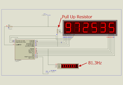
4MHz(internal OSC.)/4(working OSC)/8(prescaler)/256(max counts of TMR0)/6(number of digits) = 81.3 Hz which is good for a display.
Just an example, I have implemented (in Proteus) a 999999-second counter by using 6 Digits LED 7-Segment Multiplexing technique. There are 2 main components in the project, PIC16F627A or PIC16F628 and 6 x LED7-segment display. The schematic shows below. The crystal is 32.768KHz as usual. There is a 10KOhm pull up resistor at RA4 pin as this pin is an open-drain pin as I described in "Open-Drain RA4 pin on PIC Microcontroller".

The source code in MikroC is listed below: (.hex is also available, please feel free to contact me)
//PIC16F627A
//4MHz Internal OSC
//MUX by the MUC itself with Interrupt
//TMR0 .. check the prescelar+delay in scan routine as they are related
//punkky@gmail.com
unsigned short number [10] = {
0x5F, 0x06, 0x9b, 0x8f, 0xC6, 0xCd, 0xDD, 0x07,
0xDf, 0xCf
};
unsigned short digit [6];
unsigned short counter;
unsigned short shift_register;
unsigned short x1;
unsigned short x2;
unsigned short x3;
unsigned short x4;
unsigned short x5;
unsigned short x6;
unsigned short tick;
void interrupt ()
{
if (INTCON.T0IF)
{
//Scan digits with TMR0
INTCON.T0IF = 0;
if (counter == 5)
{
PORTA = number [digit [counter]];
Delay_us (500);
shift_register = 0x01;
PORTB = ~shift_register;
PORTA = 0x00;
counter = 0;
} else
{
PORTA = number [digit [counter]];
Delay_us (500);
shift_register = shift_register << 1;
PORTB = ~shift_register;
PORTA = 0x00;
counter ++;
}
}
if (PIR1.TMR1IF)
{
TMR1H = 0x80;
PIR1.TMR1IF = 0;
tick = 1;
//update current time
x6 ++;
if (x6 > 9)
{
x6 = 0;
x5 ++;
if (x5 > 9)
{
x5 = 0;
x4 ++;
if (x4 > 9)
{
x4 = 0;
x3 ++;
if (x3 > 9)
{
x3 = 0;
x2 ++;
if (x2 > 9)
{
x2 = 0;
x1 ++;
if (x1 > 9)
{
x1 = 0;
}
}
}
}
}
}
}
}
void main ()
{
//Digital I/O for PORTA
CMCON = 0x07;
TRISA = 0x00;
PORTA = 0x00;
TRISB = 0x00;
PORTB = 0x00;
//Internal Clock 4MHz
PCON.OSCF = 1;
counter = 0;
// Enable TMR0
OPTION_REG.T0CS = 0;
// Enable Prescaler
OPTION_REG.PSA = 0;
// PS0,1,2 = 010 = 3
// 3 means 1:8 prescaler
// 1:2, 1:4, 1:8, 1:16, 1:32, 1:64, 1:128, 1:256
OPTION_REG.PS2 = 0;
OPTION_REG.PS1 = 1;
OPTION_REG.PS0 = 0;
INTCON.T0IF = 0;
INTCON.T0IE = 1;
INTCON.GIE = 1;
INTCON.PEIE = 1;
T1CON = 0x0F;
TMR1H = 0x80;
TMR1L = 0x00;
// Enable TMR1 interrupt
PIE1.TMR1IE = 1;
shift_register = 0x01;
x1 = 0;
x2 = 0;
x3 = 0;
x4 = 0;
x5 = 0;
x6 = 0;
while (1)
{
if (tick)
{
tick = 0;
//update digits
digit [0] = x1;
digit [1] = x2;
digit [2] = x3;
digit [3] = x4;
digit [4] = x5;
digit [5] = x6;
}
}
}


3 comments:
Could you also save several pins by selecting the appropriate CD4543 using a Decade Counter that reset after the sixth output?
You would only need one output from the PIC which clocked the decade counter.
I am a newbie and have often wondered if that would work - I keep meaning to try it.
Sorry, my English is not good, hope you will understand !
Will this circuit on the possibility of changing the up counters, repeatedly push switch, display will be 000001 until 999999
Please guide, thanks you
i need to do an electronic speedometer using pic16f876. my big problem is when i try to do the counter. Could u tell me if i can adapt this code to my need?
thx in advance.
Post a Comment