Monday, October 18, 2010
1.5V to 5V DC-DC Convertor
I was looking for a simple solution for pumping 1.5 volts to 5 Volts. I have designed various 1.5v- 5V DC-DC Convertors by using special purpose chips. The problem was those chips are very difficult to obtain. Moreover, DC-DC Convertors are mostly required to use coil which is also difficult to get.
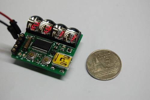
Luckily, I found this small breakout board in a local electronics shop (NPE). It was cheap, about USD 10 and small enough to fit in watch case (in the future).
The instruction is very simple, put 1.5 Volt in your will get 5V at the output.
By using this breakout board with my USB battery charger
Attaching this module to my digital wristwatch, then I have a working digital wristwatch. It can be charged via USB. Fully charged batter will make the watch lasts for 10-12 Hours (the display is always on). Now, it needs good case + strap. I have idea but don't have time to continue the project.
I have a plan to disclose the making process and give away the PCBs. But, there are some mistakes in the PCB. The problems can be resolved via firmware. However, I think it's not good to give away the incorrect PCBs. Please wait for the good PCBs and I'll give away some.
Luckily, I found this small breakout board in a local electronics shop (NPE). It was cheap, about USD 10 and small enough to fit in watch case (in the future).
The instruction is very simple, put 1.5 Volt in your will get 5V at the output.
By using this breakout board with my USB battery charger
Attaching this module to my digital wristwatch, then I have a working digital wristwatch. It can be charged via USB. Fully charged batter will make the watch lasts for 10-12 Hours (the display is always on). Now, it needs good case + strap. I have idea but don't have time to continue the project.
I have a plan to disclose the making process and give away the PCBs. But, there are some mistakes in the PCB. The problems can be resolved via firmware. However, I think it's not good to give away the incorrect PCBs. Please wait for the good PCBs and I'll give away some.
Topics:
DC-DC Convertor
Free Circuit Simulator Software
My list of Free Circuit Simulator Software
- Multisim Free Version
- Many types of simulators from Linear Technology
- LTspice IV (Switchercad) is free and powerful. It features all IC chips from Linear Technology. SwitcherCAD™ III is a fully functional Spice III simulator with enhancements and models for easing the simulation of switching regulators. This Spice is a high performance circuit simulator, integrated waveform viewer, which also includes schematic capture. Our enhancements to Spice have made simulating switching regulators extremely fast compared to normal Spice simulators. Included in this download are Spice, Macro Models for 80% of Linear Technology's switching regulators and over 200 op amp models. Furthermore, resistors, transistors and MOSFET models are included as part of this package. With this Spice simulation, viewing of the waveforms of most switching regulators can be achieved in a few minutes on a high performance PC. Also, full circuits using op amps or transistors can easily be simulated.
- Intusoft ICAP4 Demos : A lot of limitations
Topics:
Circuit Simulation,
Circuit Simulator
Friday, May 21, 2010
DIY LED Watch vs Panerai PAM 127
I have completed a prototype of my LED Watch. I will post the detail about how to make it later. The watch case and strap are missing :)
Features:
- Programmable (via ICSP)
- Vintage 7-segment LEDs with slim sigments
- Powered from a coin cell 3.7V Li-ion rechargeable battery
- Built-in USB battery charger
Size comparison between the DIY LED Watch size and a 1 Thai Baht coin.

On my wrist with help of transparent tape :).

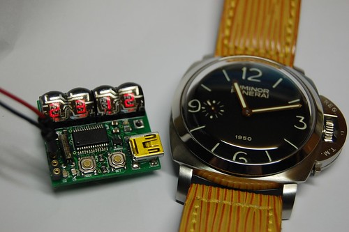
The LED Watch prototype is on the left. Panerai PAM 127 or the "Fiddy" is on the right. In case that you are wondering about the strap, it is custom made from a Louis Vuitton bag.

Please comeback and check out for the making of DIY LED Watch later.
Features:
- Programmable (via ICSP)
- Vintage 7-segment LEDs with slim sigments
- Powered from a coin cell 3.7V Li-ion rechargeable battery
- Built-in USB battery charger
Size comparison between the DIY LED Watch size and a 1 Thai Baht coin.
On my wrist with help of transparent tape :).
The LED Watch prototype is on the left. Panerai PAM 127 or the "Fiddy" is on the right. In case that you are wondering about the strap, it is custom made from a Louis Vuitton bag.
Please comeback and check out for the making of DIY LED Watch later.
Topics:
7-Segment,
Clock,
Microcontroller
Sunday, January 3, 2010
Eagle negative PCB output for printing
To make a PCB by using Dry Film photo resist, I need the PCB layout in negative mode. However, in Eagle PCB design software, I cannot print the PCB design in negative mode directly. After a few searches, I have found a good way to get negative films of my PCB designs from Eagle PCB software and it is very easy. There are 3 steps.
1. Click ‘CAM’ on the menu bar
2. Select ‘PS_INVERTED’ as the output device and then select layers that you want to export
3. Click ‘Process Job’ and it’s done!
The output is ‘yourfile.eps’ which is an encapsulated PostScript. You can use Adobe Illustrator or similar Vector based graphics applications to view/edit/print it.
Sunday, November 29, 2009
I'm still alive
Just to let you know that I'm still alive. I'm just too busy (with my child and paid works). However, I have done some microcontroller projects. Yes, they are clock/watch related projects. I also want to complete many projects that the concepts have been proved for example, GPS Clock, Digital Wristwatch etc.,
By the way, I have got many friends via this blog.
Thank you all of you who sending me emails.
By the way, I have got many friends via this blog.
Thank you all of you who sending me emails.
Tuesday, August 4, 2009
Small LED dot matrix development board
I was very busy for the past two months so this blog just didn't move. As you may know, the LED dot matrix display is my favorite device. I have designed a small development board for testing my led dot matrix related programs.
The schematic is as the following:

The PCB is single sided so I can make it at home. Most of the components are SMD to keep small footprint of the board. The PCB size: 58.4mm x 46mm

Acutally, I made a PCB and installed all components but the board didn't work :p. It was working when I tested the schematic on breadboard (with through hole version of PIC16F887). I think the SMD PIC16F887 may be broken or the PCB is bad but I just don't have time to figure out the problem. I will try new PCB and PIC16F887.
The schematic is as the following:

The PCB is single sided so I can make it at home. Most of the components are SMD to keep small footprint of the board. The PCB size: 58.4mm x 46mm

Acutally, I made a PCB and installed all components but the board didn't work :p. It was working when I tested the schematic on breadboard (with through hole version of PIC16F887). I think the SMD PIC16F887 may be broken or the PCB is bad but I just don't have time to figure out the problem. I will try new PCB and PIC16F887.
Topics:
Dot Matrix,
led,
PCB,
PIC16F887,
Schematic
Sunday, May 17, 2009
USB Coin/Button Cell Battery Charger
I have designed many small footprint PIC projects (such as, pocket watches and wristwatches) but I cannot make them really portable. To make them portable, I need small power sources. Of course, Coin Cell battery would be the smallest DC source that I can buy. The problem is that a Lithium button cell provides 3 V. which is not enough to drive my projects. I thought about using DC-DC step-up converter to boost 3 V. to 5 V. However, it's a little bit complex to add DC-DC converter to the projects. Moreover, my projects consume a lot of power as they consist of many LEDs, a button battery will not last for a day. So, I stopped my think at that point.
Just recently, I have found a rechargeable coin cell battery at Sparkfun.com. It provides 3.7 V. at 200mAh. I don't know that my projects will work at 3.7 V. or not. But, I want to give it a try. For portability, I want to charge the battery from my computer's USB port. So, I designed a USB coin cell battery + charger breakout board. Like many simple battery charger, I use MAX 1555 as the controller of the charger.
The schematic:

The single sided PCB (40mm x 30mm):

The LED goes off when the battery is fully charged (but the charger is still charging).
Please note that the schematic/PCB are just the design and I haven't made it yet. The parts are ordered and I will update when I complete the hardware.
Just recently, I have found a rechargeable coin cell battery at Sparkfun.com. It provides 3.7 V. at 200mAh. I don't know that my projects will work at 3.7 V. or not. But, I want to give it a try. For portability, I want to charge the battery from my computer's USB port. So, I designed a USB coin cell battery + charger breakout board. Like many simple battery charger, I use MAX 1555 as the controller of the charger.
The schematic:

The single sided PCB (40mm x 30mm):

The LED goes off when the battery is fully charged (but the charger is still charging).
Please note that the schematic/PCB are just the design and I haven't made it yet. The parts are ordered and I will update when I complete the hardware.
Topics:
Battery Charger,
Electronics,
Schematic
Tuesday, April 14, 2009
Classic LED 7-Segment Displays
Just recently I have been addicted to old LED displays as they are small and bright and I love the classic look. We can see them in vintage calculators and vintage led watches. However these displays consume significant amount of power, so they are not used in watches and calculators anymore. As they are replaced by LCD, these LED 7-Segment displays are not in production anymore and difficult to obtain.
Now, I have 2 models of the classic LED 7-Segment as shown in the picture below: HP 5082-7414 from HP is on the left. It’s a 4-digit Red LED 7-Segment very nice for wristwatch. The one on the right is an 2-digit Red LED 7-Segment from an unknown maker. It can be used in a wristwatch too (with a little bit bigger case).

Based on my inspection, I have made symbols for these displays with Eagle 5.4.0 free version. The displays are common cathode and the symbols are below

The PCB footprints are as the following (DIP 12)

I have made simple clocks using these displays and PIC16F887. The real thing looks much better than the photo. The displays are bright red and sun light viewable. Very COOL!!! They are on my computer desk and I love to see them very often.


Each clock consumes about 0.25W (50mA, 5V) when the PIC16F887 operates at 250kHz (display refresh rate is about 61Hz). The amount of consumed current can be reduced significantly if I use some current limit resistors. But the displays will be dimmer than without resistors. I will try to use PWM for reducing the power consumption as I don’t want to put 8 resistors into my design. The schematic/PCB and firmware including source code in MikroC will be made public once I have complete all of the designs. I will even have kits for sell if my time permitted.
Now, I have 2 models of the classic LED 7-Segment as shown in the picture below: HP 5082-7414 from HP is on the left. It’s a 4-digit Red LED 7-Segment very nice for wristwatch. The one on the right is an 2-digit Red LED 7-Segment from an unknown maker. It can be used in a wristwatch too (with a little bit bigger case).
Based on my inspection, I have made symbols for these displays with Eagle 5.4.0 free version. The displays are common cathode and the symbols are below
The PCB footprints are as the following (DIP 12)
I have made simple clocks using these displays and PIC16F887. The real thing looks much better than the photo. The displays are bright red and sun light viewable. Very COOL!!! They are on my computer desk and I love to see them very often.
Each clock consumes about 0.25W (50mA, 5V) when the PIC16F887 operates at 250kHz (display refresh rate is about 61Hz). The amount of consumed current can be reduced significantly if I use some current limit resistors. But the displays will be dimmer than without resistors. I will try to use PWM for reducing the power consumption as I don’t want to put 8 resistors into my design. The schematic/PCB and firmware including source code in MikroC will be made public once I have complete all of the designs. I will even have kits for sell if my time permitted.
Wednesday, March 11, 2009
Setting Internal Oscillator for PIC16F627A
I love to use PIC16F627A and PIC16F628 because they come with internal oscillators. That means I can make a project with lower component count (without 1 crystal and 2 load capacitors). The project setting of MikroC for using internal oscillator of the PIC16F627A shows below:
Topics:
MikroC,
PIC16F627a,
PIC16F628
Saturday, March 7, 2009
Multisim Analog Devices Edition 10.0 Free Download
I have found a good and free circuit simulator,Multisim Analog Devices Edition 10.0. As you may know that Multisim is a famous electronics circuit simulation software (circuit simulator). It's based on Electronics Workbench from the same company. I have found the free version (not the cracked version) of Multisim by chance and you may not find it on the National Instruments website. It comes with a lot of measurement tools and it's very easy to use. I use it to simulate various analog circuits. The image below shows the screen shot of the simulation of DC-Boost Converter (12V to 150V step up).

Not only analog circuit, but it also simulates digital circuit as one may call it 'Mixed-Mode Simulator'.
Some features and limitations:
Please follow the link for Free Download Multisim 183MB

Not only analog circuit, but it also simulates digital circuit as one may call it 'Mixed-Mode Simulator'.
Some features and limitations:
- Build simulated component evaluation circuits to quickly assess behavior of over 800 Analog Devices operational amplifiers, switches and voltage references
- Examine the unit under test in the intended circuit topology with up to 25 components
- Use built-in instruments and analyses including oscilloscopes and worst-case analysis
- Swap components easily to pinpoint best design options
- Link to the Analog Devices Design Center for more online evaluation tools
- Instantly access product pages and datasheets of each Analog Devices component
- Upgrade to a full edition of NI Multisim to complete designs and transfer to board layout with NI Ultiboard
Please follow the link for Free Download Multisim 183MB
Topics:
Circuit Simulation,
Circuit Simulator,
Electronics
Friday, February 20, 2009
1Hz Clock Generator using PIC12F675
Based on the idea from http://www.josepino.com/pic_projects/?timebaseI have created a 1Hz Clock Generator. I use PIC12F675 as it's available locally. Its price is just about US$1.
The concept is using 32.768kHz crystal as a clock for the PIC. Therefor, the internal instruction clock is 32768/4 = 8192 Hz. By using the 16 bit Timer1 to count the instruction clock cycles, the interrupt will occur every 8 second. This period can be reduced by setting initial value of the Timer1 (TMR1H:TMR1L). I have to make Timer1 to count up to 8192 for generating overflow interrupt every 1 second. To make Timer1 count up to 8192, the initial value of TMR1 must be 65536-8192 = 57344 or 0xE000. This means TMR1H = 0xE0 and TMR1L = 0x00. In this case, I need to set only the TMR1H=0xE0 and let TMR1L runs continuously. By changing the initial value of Timer1, I can generate almost any frequencies.
An application for this project is a precise 1Hz blinking LED signal :) ha ha. I know that it's not useful but I think it's fun to look at (am I crazy?). Another application is a precise 1Hz time base for a clock.
The source code is written in MikroC.
// PIC12F675
// 1Hz Time Base Osc.
// Timer1 Module
// 32.768 KHz
unsigned short tick;
void Init ();
void interrupt ()
{
if (PIR1.TMR1IF)
{
TMR1H = 0xE0;
PIR1.TMR1IF = 0;
tick = 1;
}
}
void main ()
{
tick = 0;
//Initialize Ports and Timer1 Module
Init ();
while (1)
{
if (tick)
{
tick = 0;
GPIO = (1 << 2);
}
if (TMR1H > 0xF0)
{
GPIO = 0;
}
}
}
void Init ()
{
TRISIO = 0;
//Make all pins as output ports
GPIO = 0;
//Use Timer1 module
INTCON.GIE = 1;
INTCON.PEIE = 1;
T1CON = 0x01;
//Overflow every 8192
TMR1H = 0xE0;
TMR1L = 0x00;
// Enable TMR1 interrupt
PIE1.TMR1IE = 1;
}
The schematic is as the following image.

The PCB:

3D version:
The concept is using 32.768kHz crystal as a clock for the PIC. Therefor, the internal instruction clock is 32768/4 = 8192 Hz. By using the 16 bit Timer1 to count the instruction clock cycles, the interrupt will occur every 8 second. This period can be reduced by setting initial value of the Timer1 (TMR1H:TMR1L). I have to make Timer1 to count up to 8192 for generating overflow interrupt every 1 second. To make Timer1 count up to 8192, the initial value of TMR1 must be 65536-8192 = 57344 or 0xE000. This means TMR1H = 0xE0 and TMR1L = 0x00. In this case, I need to set only the TMR1H=0xE0 and let TMR1L runs continuously. By changing the initial value of Timer1, I can generate almost any frequencies.
An application for this project is a precise 1Hz blinking LED signal :) ha ha. I know that it's not useful but I think it's fun to look at (am I crazy?). Another application is a precise 1Hz time base for a clock.
The source code is written in MikroC.
// PIC12F675
// 1Hz Time Base Osc.
// Timer1 Module
// 32.768 KHz
unsigned short tick;
void Init ();
void interrupt ()
{
if (PIR1.TMR1IF)
{
TMR1H = 0xE0;
PIR1.TMR1IF = 0;
tick = 1;
}
}
void main ()
{
tick = 0;
//Initialize Ports and Timer1 Module
Init ();
while (1)
{
if (tick)
{
tick = 0;
GPIO = (1 << 2);
}
if (TMR1H > 0xF0)
{
GPIO = 0;
}
}
}
void Init ()
{
TRISIO = 0;
//Make all pins as output ports
GPIO = 0;
//Use Timer1 module
INTCON.GIE = 1;
INTCON.PEIE = 1;
T1CON = 0x01;
//Overflow every 8192
TMR1H = 0xE0;
TMR1L = 0x00;
// Enable TMR1 interrupt
PIE1.TMR1IE = 1;
}
The schematic is as the following image.

The PCB:

3D version:
Topics:
Clock,
Microcontroller,
PCB,
Schematic,
Source Code
Wednesday, February 11, 2009
Transistor array
I am looking for transistor arrays for my LED projects as I want to reduce number of components on board. After some searches, I have found that there are two candidates for current source and sink transistor arrays as the following:
UDN2981 : 8 channels high current source MAX 500mA

ULN2003 : 7 channels high current sink MAX 500mA

I will use these transistor arrays for driving large 7-segment display panel , bright led dot matrix panel and other LED projects.
UDN2981 : 8 channels high current source MAX 500mA

ULN2003 : 7 channels high current sink MAX 500mA

I will use these transistor arrays for driving large 7-segment display panel , bright led dot matrix panel and other LED projects.
Topics:
Electronics
Sunday, January 25, 2009
3D Electronics Design
I just found a new thing to play with, 3D Electronics Design. I have seen some great 3D images of electronics component design for sometimes but I couldn't figure how they were made. Below image is one of my favorite. Please see http://www.blueroomelectronics.com/ for more images.

I have been playing with Eagle3D for sometimes. However, I cannot manipulate my design interactively and cannot export models to render in other 3D renderers. Just today, I found that blueroomelectronics's designs were made with Google SketchUp. So, I downloaded and installed it. The software is very easy to use. But, there is no electronics component library. However, there are some components available for you to download from google 3D warehouse. If you want anything that not available in the google 3D warehouse, you have to make it by yourself.
Below is my first try on making a PIC16F887 with TQFP-44 package.

I hope that I will come up with complete 3D designs of my clock projects. It's very fun to do these things.

I have been playing with Eagle3D for sometimes. However, I cannot manipulate my design interactively and cannot export models to render in other 3D renderers. Just today, I found that blueroomelectronics's designs were made with Google SketchUp. So, I downloaded and installed it. The software is very easy to use. But, there is no electronics component library. However, there are some components available for you to download from google 3D warehouse. If you want anything that not available in the google 3D warehouse, you have to make it by yourself.
Below is my first try on making a PIC16F887 with TQFP-44 package.

I hope that I will come up with complete 3D designs of my clock projects. It's very fun to do these things.
Things to do
There are requests from readers as the following:
1. Complete project of the GPS clock
2. Adding calendar to my Digital Clock
3. Full function DS1307 Clock
And my own to do list:
4. FM Radio
5. Nixie Clock
6. Chronograph (stop watch)
7. Digital clock with 7-segment multiplexing using PIC16F627a or PIC16F628 + DS1307 + DS18S20 (Clock+Thermometer)
8. Digital clock + radio + thermometer (PIC16F887 + DS1307 + DS18S20 + Radio chip)
9. Complete led dot matrix clock
10.16x16 Led Dot matrix display
1. Complete project of the GPS clock
2. Adding calendar to my Digital Clock
3. Full function DS1307 Clock
And my own to do list:
4. FM Radio
5. Nixie Clock
6. Chronograph (stop watch)
7. Digital clock with 7-segment multiplexing using PIC16F627a or PIC16F628 + DS1307 + DS18S20 (Clock+Thermometer)
8. Digital clock + radio + thermometer (PIC16F887 + DS1307 + DS18S20 + Radio chip)
9. Complete led dot matrix clock
10.16x16 Led Dot matrix display
Wednesday, January 21, 2009
2-digit BCD to decimal conversion
Now, I'm working on the full feature clock using DS1307. In the clock, I use many BCD to decimal (bcd2dec) and decimal to BCD conversions for reading and setting time of the DS1307 RTC. MikroC provides buit-in functions for these conversions but the functions consume modest amount of MCU memory space. I have came up with simple functions that consume less memory for doing 2-digit BCD to decimal and the reverse conversions.
2-digit BCD to Decimal conversion function:
Example: myBcd2Dec(01000101) = 45
2-digit Decimal to BCD conversion function:
Example: myDec2Bcd(45) = 01000101
2-digit BCD to Decimal conversion function:
unsigned short myBcd2Dec(unsigned short bcd){
return ((bcd >> 4)*10+(bcd & 0x0F));
}
return ((bcd >> 4)*10+(bcd & 0x0F));
}
Example: myBcd2Dec(01000101) = 45
2-digit Decimal to BCD conversion function:
unsigned short myDec2Bcd(unsigned short dec){
return (((dec/10)<<4)(dec%10));
}
return (((dec/10)<<4)(dec%10));
}
Example: myDec2Bcd(45) = 01000101
Topics:
DS1307,
Microcontroller,
MikroC,
Source Code
Sunday, January 11, 2009
Square Wave output from DS1307
For the clock that uses DS1307 RTC chip, I want a blinking led for indication of second. So, I have placed a resistor and an LED to pin 7 (SQW/OUT) of the DS1307 like below schematic:
With this configuration (hardware+software), the LED was blinking at 1 time/second but the blink pattern was not my expectation. The LED is Off when the clock is updated and it is On at 0.5 second later. Quoted from the Control Register section of the DS1307's Datasheet:
I want the reverse pattern (the LED is On when the time is updated and it is Off at 0.5 second later). So, I will add an invert logic before the LED like:

I have a plan to use this square wave output of the DS1307 for generating an interrupt to instruct the MCU to read time from the DS1307 and I will keep in mind that "The clock is updated at the falling edge of the square wave". The complete clock will be posted here later.
With this configuration (hardware+software), the LED was blinking at 1 time/second but the blink pattern was not my expectation. The LED is Off when the clock is updated and it is On at 0.5 second later. Quoted from the Control Register section of the DS1307's Datasheet:
With the square wave output set to 1Hz, the clock registers update on the falling edge of the square wave.
I want the reverse pattern (the LED is On when the time is updated and it is Off at 0.5 second later). So, I will add an invert logic before the LED like:

I have a plan to use this square wave output of the DS1307 for generating an interrupt to instruct the MCU to read time from the DS1307 and I will keep in mind that "The clock is updated at the falling edge of the square wave". The complete clock will be posted here later.
Topics:
DS1307
Monday, January 5, 2009
A Simple Clock using DS1307 + PIC16F877A
Even I have posted about "DS1307 + PIC16F877A", I didn't have chance to make a real prototype of the clock. I have done only on the simulation software. Today, I have received a comment about that post. ah_bear followed my code and schematic on that post but the clock didn't work. This is because the code on that post is for reading time from DS1307 so there must be some values in the DS1307 before you can read. The solution is simple. Just place setting time codes before reading codes.
This time, I have made a real prototype to confirm that it's working. There is no setting buttons. If you want to make a real usable clock you have to implement the button interfaces (I may make one and post it here). The photo of my working prototype is featured below. Please check out my flikr at http://flickr.com/photos/punkky/ for more photos.

The schematic of the clock is very simple. Please note that the schematic does not show power supply to the PIC16F877A and the DS1307, you have to connect them by youself. If you are new to PIC/LCD interface please see MikroC "Hello World!" LCD example .

The source code:
This time, I have made a real prototype to confirm that it's working. There is no setting buttons. If you want to make a real usable clock you have to implement the button interfaces (I may make one and post it here). The photo of my working prototype is featured below. Please check out my flikr at http://flickr.com/photos/punkky/ for more photos.

The schematic of the clock is very simple. Please note that the schematic does not show power supply to the PIC16F877A and the DS1307, you have to connect them by youself. If you are new to PIC/LCD interface please see MikroC "Hello World!" LCD example .

The source code:
//Sample code for
//DS1307 RTC Interfacing with PIC16F877A
//Coded by punkky@gmail.com
//Compiler: mikroC 8.0.0
//http://picnote.blogspot.com
//05/01/2009
//Use with your own risk
unsigned short read_ds1307(unsigned short address );
void write_ds1307(unsigned short address,unsigned short w_data);
unsigned short sec;
unsigned short minute;
unsigned short hour;
unsigned short day;
unsigned short date;
unsigned short month;
unsigned short year;
unsigned short data;
char time[9];
char ddate[11];
unsigned char BCD2UpperCh(unsigned char bcd);
unsigned char BCD2LowerCh(unsigned char bcd);
void main(){
I2C_Init(100000); //DS1307 I2C is running at 100KHz
PORTB = 0;
TRISB = 0; // Configure PORTB as output
TRISC = 0xFF;
Lcd_Init(&PORTB); // Initialize LCD connected to PORTB
Lcd_Cmd(Lcd_CLEAR); // Clear display
Lcd_Cmd(Lcd_CURSOR_OFF); // Turn cursor off
Lcd_Out(1, 1, "TIME:");
Lcd_Out(2, 1, "DATE:");
//Set Time
write_ds1307(0,0x80); //Reset second to 0 sec. and stop Oscillator
write_ds1307(1,0x10); //write min 27
write_ds1307(2,0x01); //write hour 14
write_ds1307(3,0x02); //write day of week 2:Monday
write_ds1307(4,0x05); // write date 17
write_ds1307(5,0x01); // write month 6 June
write_ds1307(6,0x09); // write year 8 --> 2008
write_ds1307(7,0x10); //SQWE output at 1 Hz
write_ds1307(0,0x00); //Reset second to 0 sec. and start Oscillator
while(1)
{
sec=read_ds1307(0); // read second
minute=read_ds1307(1); // read minute
hour=read_ds1307(2); // read hour
day=read_ds1307(3); // read day
date=read_ds1307(4); // read date
month=read_ds1307(5); // read month
year=read_ds1307(6); // read year
time[0] = BCD2UpperCh(hour);
time[1] = BCD2LowerCh(hour);
time[2] = ':';
time[3] = BCD2UpperCh(minute);
time[4] = BCD2LowerCh(minute);
time[5] = ':';
time[6] = BCD2UpperCh(sec);
time[7] = BCD2LowerCh(sec);
time[8] = '\0';
ddate[0] = BCD2UpperCh(date);
ddate[1] = BCD2LowerCh(date);
ddate[2] ='/';
ddate[3] = BCD2UpperCh(month);
ddate[4] = BCD2LowerCh(month);
ddate[5] ='/';
ddate[6] = '2';
ddate[7] = '0';
ddate[8] = BCD2UpperCh(year);
ddate[9] = BCD2LowerCh(year);
ddate[10] = '\0';
Lcd_Out(1,6,time);
Lcd_Out(2,6,ddate);
Delay_ms(50);
}
}
unsigned short read_ds1307(unsigned short address)
{
I2C_Start();
I2C_Wr(0xd0); //address 0x68 followed by direction bit (0 for write, 1 for read) 0x68 followed by 0 --> 0xD0
I2C_Wr(address);
I2C_Repeated_Start();
I2C_Wr(0xd1); //0x68 followed by 1 --> 0xD1
data=I2C_Rd(0);
I2C_Stop();
return(data);
}
unsigned char BCD2UpperCh(unsigned char bcd)
{
return ((bcd >> 4) + '0');
}
unsigned char BCD2LowerCh(unsigned char bcd)
{
return ((bcd & 0x0F) + '0');
}
void write_ds1307(unsigned short address,unsigned short w_data)
{
I2C_Start(); // issue I2C start signal
//address 0x68 followed by direction bit (0 for write, 1 for read) 0x68 followed by 0 --> 0xD0
I2C_Wr(0xD0); // send byte via I2C (device address + W)
I2C_Wr(address); // send byte (address of DS1307 location)
I2C_Wr(w_data); // send data (data to be written)
I2C_Stop(); // issue I2C stop signal
}
//DS1307 RTC Interfacing with PIC16F877A
//Coded by punkky@gmail.com
//Compiler: mikroC 8.0.0
//http://picnote.blogspot.com
//05/01/2009
//Use with your own risk
unsigned short read_ds1307(unsigned short address );
void write_ds1307(unsigned short address,unsigned short w_data);
unsigned short sec;
unsigned short minute;
unsigned short hour;
unsigned short day;
unsigned short date;
unsigned short month;
unsigned short year;
unsigned short data;
char time[9];
char ddate[11];
unsigned char BCD2UpperCh(unsigned char bcd);
unsigned char BCD2LowerCh(unsigned char bcd);
void main(){
I2C_Init(100000); //DS1307 I2C is running at 100KHz
PORTB = 0;
TRISB = 0; // Configure PORTB as output
TRISC = 0xFF;
Lcd_Init(&PORTB); // Initialize LCD connected to PORTB
Lcd_Cmd(Lcd_CLEAR); // Clear display
Lcd_Cmd(Lcd_CURSOR_OFF); // Turn cursor off
Lcd_Out(1, 1, "TIME:");
Lcd_Out(2, 1, "DATE:");
//Set Time
write_ds1307(0,0x80); //Reset second to 0 sec. and stop Oscillator
write_ds1307(1,0x10); //write min 27
write_ds1307(2,0x01); //write hour 14
write_ds1307(3,0x02); //write day of week 2:Monday
write_ds1307(4,0x05); // write date 17
write_ds1307(5,0x01); // write month 6 June
write_ds1307(6,0x09); // write year 8 --> 2008
write_ds1307(7,0x10); //SQWE output at 1 Hz
write_ds1307(0,0x00); //Reset second to 0 sec. and start Oscillator
while(1)
{
sec=read_ds1307(0); // read second
minute=read_ds1307(1); // read minute
hour=read_ds1307(2); // read hour
day=read_ds1307(3); // read day
date=read_ds1307(4); // read date
month=read_ds1307(5); // read month
year=read_ds1307(6); // read year
time[0] = BCD2UpperCh(hour);
time[1] = BCD2LowerCh(hour);
time[2] = ':';
time[3] = BCD2UpperCh(minute);
time[4] = BCD2LowerCh(minute);
time[5] = ':';
time[6] = BCD2UpperCh(sec);
time[7] = BCD2LowerCh(sec);
time[8] = '\0';
ddate[0] = BCD2UpperCh(date);
ddate[1] = BCD2LowerCh(date);
ddate[2] ='/';
ddate[3] = BCD2UpperCh(month);
ddate[4] = BCD2LowerCh(month);
ddate[5] ='/';
ddate[6] = '2';
ddate[7] = '0';
ddate[8] = BCD2UpperCh(year);
ddate[9] = BCD2LowerCh(year);
ddate[10] = '\0';
Lcd_Out(1,6,time);
Lcd_Out(2,6,ddate);
Delay_ms(50);
}
}
unsigned short read_ds1307(unsigned short address)
{
I2C_Start();
I2C_Wr(0xd0); //address 0x68 followed by direction bit (0 for write, 1 for read) 0x68 followed by 0 --> 0xD0
I2C_Wr(address);
I2C_Repeated_Start();
I2C_Wr(0xd1); //0x68 followed by 1 --> 0xD1
data=I2C_Rd(0);
I2C_Stop();
return(data);
}
unsigned char BCD2UpperCh(unsigned char bcd)
{
return ((bcd >> 4) + '0');
}
unsigned char BCD2LowerCh(unsigned char bcd)
{
return ((bcd & 0x0F) + '0');
}
void write_ds1307(unsigned short address,unsigned short w_data)
{
I2C_Start(); // issue I2C start signal
//address 0x68 followed by direction bit (0 for write, 1 for read) 0x68 followed by 0 --> 0xD0
I2C_Wr(0xD0); // send byte via I2C (device address + W)
I2C_Wr(address); // send byte (address of DS1307 location)
I2C_Wr(w_data); // send data (data to be written)
I2C_Stop(); // issue I2C stop signal
}
Topics:
Clock,
DS1307,
Microcontroller,
PIC16F877a,
Schematic,
Source Code
Wednesday, December 31, 2008
6 Digits 7-Segment LED Multiplexing using a Shift Register
Multiplexing technique can reduce number of needed I/O pins of the MCU as I have explained in 'LED 7-Segment Multiplexing' and '6 Digits LED 7-Segment Multiplexing'. In those posts, I used 13 I/O pins for driving 6 digits LED 7-Segment. However, the PIC16F627A and PIC16F628 have only 15 usable I/O pins that include 2 pins for external 32.768KHz oscillator. So, there is no pin left for time setting buttons. I can change to the PIC that has more I/O pins, but I don't think it's a good solution. From my searches, I can overcome this I/O pins shortage problem by using shift register to expand the MCU I/O pins.
The concept is very similar to led dot matrix driving technique. Each digit is multiplexed via a shift register 74HC595 which is required 3 pins of the MCU. Each segment of the 7-segment display is driven by PORTA of the PIC16F628. As a result, the required pins for driving 6-Digit 7-Segment display are just 3+7 = 10 pins!. With this configuration, there are 3 I/O pins that are free for time setting buttons and driving blinking second LEDs.
I use TMR2 module for scanning digits. TMR2 is an 8-bit timer which overflows every 256 (0xFF) counts. It's known that the refresh rate above 50Hz would be enough for human's eyes to see the display without recognizing the flickering. If I set TMR2 with 1:8 Prescaler (T2CON = 0x3C), the multiplexing frequency will be 81.3Hz (4MHz/4/256/8/6 = 81.3Hz) which is enough for flicker free display.
PORTA is used to drive each segment of the 7-segment displays. However, I have to skip the RA5 as it's a MCLR pin and it can be only input pin. So, my 7-segment digit mask is different then the normal 7-segment digit mask.
Below is the example schematic of 999999-second counter using the PIC16F627A or PIC16F628 and a shift register. I will not implement a clock with this configuration as I need more free MCU pins for driving Alarm buzzer and other things.

The source code for 999999-second counter in MikroC is listed below
The concept is very similar to led dot matrix driving technique. Each digit is multiplexed via a shift register 74HC595 which is required 3 pins of the MCU. Each segment of the 7-segment display is driven by PORTA of the PIC16F628. As a result, the required pins for driving 6-Digit 7-Segment display are just 3+7 = 10 pins!. With this configuration, there are 3 I/O pins that are free for time setting buttons and driving blinking second LEDs.
I use TMR2 module for scanning digits. TMR2 is an 8-bit timer which overflows every 256 (0xFF) counts. It's known that the refresh rate above 50Hz would be enough for human's eyes to see the display without recognizing the flickering. If I set TMR2 with 1:8 Prescaler (T2CON = 0x3C), the multiplexing frequency will be 81.3Hz (4MHz/4/256/8/6 = 81.3Hz) which is enough for flicker free display.
PORTA is used to drive each segment of the 7-segment displays. However, I have to skip the RA5 as it's a MCLR pin and it can be only input pin. So, my 7-segment digit mask is different then the normal 7-segment digit mask.
my PORTA 7-segment digit mask : {0x5F, 0x06, 0x9b, 0x8f, 0xC6, 0xCd,0xDD, 0x07,
0xDf, 0xCf}
Normal 7-segment digit mask : {0x3f, 0x06, 0x5b, 0x4f, 0x66, 0x6d, 0x7d, 0x07, 0x7f, 0x6f} for number 0-9 respectively.
0xDf, 0xCf}
Normal 7-segment digit mask : {0x3f, 0x06, 0x5b, 0x4f, 0x66, 0x6d, 0x7d, 0x07, 0x7f, 0x6f} for number 0-9 respectively.
Below is the example schematic of 999999-second counter using the PIC16F627A or PIC16F628 and a shift register. I will not implement a clock with this configuration as I need more free MCU pins for driving Alarm buzzer and other things.

The source code for 999999-second counter in MikroC is listed below
//PIC16F627A or PIC16F628
//4MHz Internal OSC
//MUX by using Shift Register 595
// Critical parameters:
// Delay, Postscaler, Prescaler
// Low delay + High Prescaler
// 03/11/2008
// punkky@gmail.com
#define SH_CP PORTB.F0
#define DS PORTB.F1
#define ST_CP PORTB.F2
// 7-Segment code is skipping RA5, so the code is not as normal 7-segment coding
unsigned short number [10] = {
0x5F, 0x06, 0x9b, 0x8f, 0xC6, 0xCd, 0xDD, 0x07,
0xDf, 0xCf
};
unsigned short digit [6] = {
0, 0, 0, 0, 0, 0
};
unsigned short i;
unsigned short n;
unsigned short counter;
unsigned short tick;
unsigned short shift_register;
unsigned short x1;
unsigned short x2;
unsigned short x3;
unsigned short x4;
unsigned short x5;
unsigned short x6;
void interrupt ()
{
if (PIR1.TMR2IF)
{
PIR1.TMR2IF = 0;
if (counter == 5)
{
//Shift data
DS = 0;
//Store data
SH_CP = 1;
SH_CP = 0;
Delay_us (250);
counter = 0;
}else
{
//Shift data
DS = 1;
//Store
SH_CP = 1;
SH_CP = 0;
Delay_us (250);
counter ++;
}
ST_CP = 1;
ST_CP = 0;
PORTA = 0x00;
PORTA = number [digit [counter]];
}
if (PIR1.TMR1IF)
{
TMR1H = 0x80;
PIR1.TMR1IF = 0;
tick = 1;
x6 ++;
if (x6 > 9)
{
x6 = 0;
x5 ++;
if (x5 > 9)
{
x5 = 0;
x4 ++;
if (x4 > 9)
{
x4 = 0;
x3 ++;
if (x3 > 9)
{
x3 = 0;
x2 ++;
if (x2 > 9)
{
x2 = 0;
x1 ++;
if (x1 > 9)
{
x1 = 0;
}
}
}
}
}
}
}
}
void main ()
{
//Digital I/O for PORTA
CMCON = 0x07;
TRISA = 0x00;
PORTA = 0x00;
TRISB = 0x00;
PORTB = 0x00;
//Internal Clock 4MHz
PCON.OSCF = 1;
counter = 0;
// Set GIE, PEIE
INTCON = 0xC0;
//1:8 post scaler
T2CON = 0x3C;
// enable interupt
PIE1.TMR2IE = 1;
T1CON = 0x0F;
//Initial value TMR1: 0x8000
TMR1H = 0x80;
TMR1L = 0x00;
// enable interupt
PIE1.TMR1IE = 1;
//Data
DS = 0;
//Store
SH_CP = 0;
ST_CP = 0;
x1 = 0;
x2 = 0;
x3 = 0 ;
x4 = 0;
x5 = 0;
x6 = 0;
while (1)
{
if (tick)
{
tick = 0;
digit [0] = x1;
digit [1] = x2;
digit [2] = x3;
digit [3] = x4;
digit [4] = x5;
digit [5] = x6;
}
}
}
//4MHz Internal OSC
//MUX by using Shift Register 595
// Critical parameters:
// Delay, Postscaler, Prescaler
// Low delay + High Prescaler
// 03/11/2008
// punkky@gmail.com
#define SH_CP PORTB.F0
#define DS PORTB.F1
#define ST_CP PORTB.F2
// 7-Segment code is skipping RA5, so the code is not as normal 7-segment coding
unsigned short number [10] = {
0x5F, 0x06, 0x9b, 0x8f, 0xC6, 0xCd, 0xDD, 0x07,
0xDf, 0xCf
};
unsigned short digit [6] = {
0, 0, 0, 0, 0, 0
};
unsigned short i;
unsigned short n;
unsigned short counter;
unsigned short tick;
unsigned short shift_register;
unsigned short x1;
unsigned short x2;
unsigned short x3;
unsigned short x4;
unsigned short x5;
unsigned short x6;
void interrupt ()
{
if (PIR1.TMR2IF)
{
PIR1.TMR2IF = 0;
if (counter == 5)
{
//Shift data
DS = 0;
//Store data
SH_CP = 1;
SH_CP = 0;
Delay_us (250);
counter = 0;
}else
{
//Shift data
DS = 1;
//Store
SH_CP = 1;
SH_CP = 0;
Delay_us (250);
counter ++;
}
ST_CP = 1;
ST_CP = 0;
PORTA = 0x00;
PORTA = number [digit [counter]];
}
if (PIR1.TMR1IF)
{
TMR1H = 0x80;
PIR1.TMR1IF = 0;
tick = 1;
x6 ++;
if (x6 > 9)
{
x6 = 0;
x5 ++;
if (x5 > 9)
{
x5 = 0;
x4 ++;
if (x4 > 9)
{
x4 = 0;
x3 ++;
if (x3 > 9)
{
x3 = 0;
x2 ++;
if (x2 > 9)
{
x2 = 0;
x1 ++;
if (x1 > 9)
{
x1 = 0;
}
}
}
}
}
}
}
}
void main ()
{
//Digital I/O for PORTA
CMCON = 0x07;
TRISA = 0x00;
PORTA = 0x00;
TRISB = 0x00;
PORTB = 0x00;
//Internal Clock 4MHz
PCON.OSCF = 1;
counter = 0;
// Set GIE, PEIE
INTCON = 0xC0;
//1:8 post scaler
T2CON = 0x3C;
// enable interupt
PIE1.TMR2IE = 1;
T1CON = 0x0F;
//Initial value TMR1: 0x8000
TMR1H = 0x80;
TMR1L = 0x00;
// enable interupt
PIE1.TMR1IE = 1;
//Data
DS = 0;
//Store
SH_CP = 0;
ST_CP = 0;
x1 = 0;
x2 = 0;
x3 = 0 ;
x4 = 0;
x5 = 0;
x6 = 0;
while (1)
{
if (tick)
{
tick = 0;
digit [0] = x1;
digit [1] = x2;
digit [2] = x3;
digit [3] = x4;
digit [4] = x5;
digit [5] = x6;
}
}
}
Topics:
Microcontroller,
MikroC,
PIC16F627a,
PIC16F628,
Schematic,
Source Code
Saturday, December 27, 2008
Trojan Attack : Trojan.vundo
In last couple days, I have been getting headache with Trojan attack on my computer. The symptoms were a lot of Antispyware 2009 ads and other annoying popups (Browser Hijack). I started the task manager and found that iexplore.exe was running even I didn't use IE. I found some strange files in windows/system32 such as
- sakalimo.dll
- fodituva.dll
- yidaziwi.dll
- dobafigi.dll
- juvilisi.dll
- igifabod.ini
- vefiyohu.dll
- gujayiwo.dll
- titubeve.dll
I tried Trojan Hunter, NOD32 and Spybot Search&Destroy. They found some Trojans & Malwares but they could not kill the annoying popups. After some searches, I have found that I got attack from Trojan.vundo and Trojan.vundo.H . And from my searches, I found only one mulware/trojan removal program, Malwarebytes' Anti-Mulware or MBAM, from http://www.malwarebytes.org/ that can remove these Trojans.

It's FREE! I installed it and did full system scan. It took about 3 hours for my system scan. As expected, it found and removed a lot of Trojan.vundo from my machine. After cleaning those Trojans, my machine is running fine and consuming less RAM than before.
- sakalimo.dll
- fodituva.dll
- yidaziwi.dll
- dobafigi.dll
- juvilisi.dll
- igifabod.ini
- vefiyohu.dll
- gujayiwo.dll
- titubeve.dll
I tried Trojan Hunter, NOD32 and Spybot Search&Destroy. They found some Trojans & Malwares but they could not kill the annoying popups. After some searches, I have found that I got attack from Trojan.vundo and Trojan.vundo.H . And from my searches, I found only one mulware/trojan removal program, Malwarebytes' Anti-Mulware or MBAM, from http://www.malwarebytes.org/ that can remove these Trojans.

It's FREE! I installed it and did full system scan. It took about 3 hours for my system scan. As expected, it found and removed a lot of Trojan.vundo from my machine. After cleaning those Trojans, my machine is running fine and consuming less RAM than before.
Topics:
Computer
Sunday, December 21, 2008
6 Digits LED 7-Segment Multiplexing
In the post 'LED 7-Segment Multiplexing', I have explained about the concept and benefits of multiplexing. Multiplexing implementation is very similar to driving Led Dot Matrix. I use Timer0 interrupt for switching through each digit. Timer0 or TMR0 is an 8-bit timer which overflows every 256 (0xFF) counts. It's known that the refresh rate above 50Hz would be enough for human's eyes to see the display without recognizing the flickering. If I set TMR0 with 1:8 Prescaler, the multiplexing frequency will be
Just an example, I have implemented (in Proteus) a 999999-second counter by using 6 Digits LED 7-Segment Multiplexing technique. There are 2 main components in the project, PIC16F627A or PIC16F628 and 6 x LED7-segment display. The schematic shows below. The crystal is 32.768KHz as usual. There is a 10KOhm pull up resistor at RA4 pin as this pin is an open-drain pin as I described in "Open-Drain RA4 pin on PIC Microcontroller".

The source code in MikroC is listed below: (.hex is also available, please feel free to contact me)
4MHz(internal OSC.)/4(working OSC)/8(prescaler)/256(max counts of TMR0)/6(number of digits) = 81.3 Hz which is good for a display.
Just an example, I have implemented (in Proteus) a 999999-second counter by using 6 Digits LED 7-Segment Multiplexing technique. There are 2 main components in the project, PIC16F627A or PIC16F628 and 6 x LED7-segment display. The schematic shows below. The crystal is 32.768KHz as usual. There is a 10KOhm pull up resistor at RA4 pin as this pin is an open-drain pin as I described in "Open-Drain RA4 pin on PIC Microcontroller".

The source code in MikroC is listed below: (.hex is also available, please feel free to contact me)
//PIC16F627A
//4MHz Internal OSC
//MUX by the MUC itself with Interrupt
//TMR0 .. check the prescelar+delay in scan routine as they are related
//punkky@gmail.com
unsigned short number [10] = {
0x5F, 0x06, 0x9b, 0x8f, 0xC6, 0xCd, 0xDD, 0x07,
0xDf, 0xCf
};
unsigned short digit [6];
unsigned short counter;
unsigned short shift_register;
unsigned short x1;
unsigned short x2;
unsigned short x3;
unsigned short x4;
unsigned short x5;
unsigned short x6;
unsigned short tick;
void interrupt ()
{
if (INTCON.T0IF)
{
//Scan digits with TMR0
INTCON.T0IF = 0;
if (counter == 5)
{
PORTA = number [digit [counter]];
Delay_us (500);
shift_register = 0x01;
PORTB = ~shift_register;
PORTA = 0x00;
counter = 0;
} else
{
PORTA = number [digit [counter]];
Delay_us (500);
shift_register = shift_register << 1;
PORTB = ~shift_register;
PORTA = 0x00;
counter ++;
}
}
if (PIR1.TMR1IF)
{
TMR1H = 0x80;
PIR1.TMR1IF = 0;
tick = 1;
//update current time
x6 ++;
if (x6 > 9)
{
x6 = 0;
x5 ++;
if (x5 > 9)
{
x5 = 0;
x4 ++;
if (x4 > 9)
{
x4 = 0;
x3 ++;
if (x3 > 9)
{
x3 = 0;
x2 ++;
if (x2 > 9)
{
x2 = 0;
x1 ++;
if (x1 > 9)
{
x1 = 0;
}
}
}
}
}
}
}
}
void main ()
{
//Digital I/O for PORTA
CMCON = 0x07;
TRISA = 0x00;
PORTA = 0x00;
TRISB = 0x00;
PORTB = 0x00;
//Internal Clock 4MHz
PCON.OSCF = 1;
counter = 0;
// Enable TMR0
OPTION_REG.T0CS = 0;
// Enable Prescaler
OPTION_REG.PSA = 0;
// PS0,1,2 = 010 = 3
// 3 means 1:8 prescaler
// 1:2, 1:4, 1:8, 1:16, 1:32, 1:64, 1:128, 1:256
OPTION_REG.PS2 = 0;
OPTION_REG.PS1 = 1;
OPTION_REG.PS0 = 0;
INTCON.T0IF = 0;
INTCON.T0IE = 1;
INTCON.GIE = 1;
INTCON.PEIE = 1;
T1CON = 0x0F;
TMR1H = 0x80;
TMR1L = 0x00;
// Enable TMR1 interrupt
PIE1.TMR1IE = 1;
shift_register = 0x01;
x1 = 0;
x2 = 0;
x3 = 0;
x4 = 0;
x5 = 0;
x6 = 0;
while (1)
{
if (tick)
{
tick = 0;
//update digits
digit [0] = x1;
digit [1] = x2;
digit [2] = x3;
digit [3] = x4;
digit [4] = x5;
digit [5] = x6;
}
}
}
//4MHz Internal OSC
//MUX by the MUC itself with Interrupt
//TMR0 .. check the prescelar+delay in scan routine as they are related
//punkky@gmail.com
unsigned short number [10] = {
0x5F, 0x06, 0x9b, 0x8f, 0xC6, 0xCd, 0xDD, 0x07,
0xDf, 0xCf
};
unsigned short digit [6];
unsigned short counter;
unsigned short shift_register;
unsigned short x1;
unsigned short x2;
unsigned short x3;
unsigned short x4;
unsigned short x5;
unsigned short x6;
unsigned short tick;
void interrupt ()
{
if (INTCON.T0IF)
{
//Scan digits with TMR0
INTCON.T0IF = 0;
if (counter == 5)
{
PORTA = number [digit [counter]];
Delay_us (500);
shift_register = 0x01;
PORTB = ~shift_register;
PORTA = 0x00;
counter = 0;
} else
{
PORTA = number [digit [counter]];
Delay_us (500);
shift_register = shift_register << 1;
PORTB = ~shift_register;
PORTA = 0x00;
counter ++;
}
}
if (PIR1.TMR1IF)
{
TMR1H = 0x80;
PIR1.TMR1IF = 0;
tick = 1;
//update current time
x6 ++;
if (x6 > 9)
{
x6 = 0;
x5 ++;
if (x5 > 9)
{
x5 = 0;
x4 ++;
if (x4 > 9)
{
x4 = 0;
x3 ++;
if (x3 > 9)
{
x3 = 0;
x2 ++;
if (x2 > 9)
{
x2 = 0;
x1 ++;
if (x1 > 9)
{
x1 = 0;
}
}
}
}
}
}
}
}
void main ()
{
//Digital I/O for PORTA
CMCON = 0x07;
TRISA = 0x00;
PORTA = 0x00;
TRISB = 0x00;
PORTB = 0x00;
//Internal Clock 4MHz
PCON.OSCF = 1;
counter = 0;
// Enable TMR0
OPTION_REG.T0CS = 0;
// Enable Prescaler
OPTION_REG.PSA = 0;
// PS0,1,2 = 010 = 3
// 3 means 1:8 prescaler
// 1:2, 1:4, 1:8, 1:16, 1:32, 1:64, 1:128, 1:256
OPTION_REG.PS2 = 0;
OPTION_REG.PS1 = 1;
OPTION_REG.PS0 = 0;
INTCON.T0IF = 0;
INTCON.T0IE = 1;
INTCON.GIE = 1;
INTCON.PEIE = 1;
T1CON = 0x0F;
TMR1H = 0x80;
TMR1L = 0x00;
// Enable TMR1 interrupt
PIE1.TMR1IE = 1;
shift_register = 0x01;
x1 = 0;
x2 = 0;
x3 = 0;
x4 = 0;
x5 = 0;
x6 = 0;
while (1)
{
if (tick)
{
tick = 0;
//update digits
digit [0] = x1;
digit [1] = x2;
digit [2] = x3;
digit [3] = x4;
digit [4] = x5;
digit [5] = x6;
}
}
}
Topics:
7-Segment,
Multiplexing,
PIC16F627a,
PIC16F628,
Schematic,
Source Code
Subscribe to:
Posts (Atom)