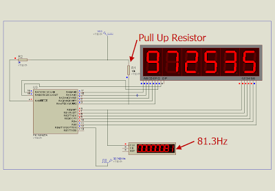
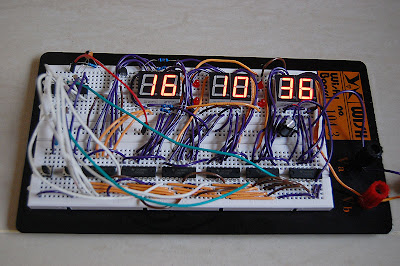
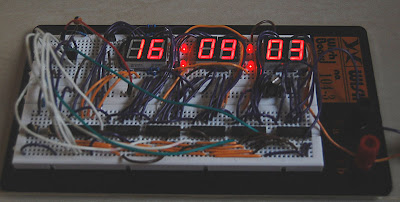
The concept is very similar to led dot matrix driving technique. Each digit is multiplexed via a shift register 74HC595 which is required 3 pins of the MCU. Each segment of the 7-segment display is driven by PORTA of the PIC16F628. As a result, the required pins for driving 6-Digit 7-Segment display are just 3+7 = 10 pins!. With this configuration, there are 3 I/O pins that are free for time setting buttons and driving blinking second LEDs.
I use TMR2 module for scanning digits. TMR2 is an 8-bit timer which overflows every 256 (0xFF) counts. It's known that the refresh rate above 50Hz would be enough for human's eyes to see the display without recognizing the flickering. If I set TMR2 with 1:8 Prescaler (T2CON = 0x3C), the multiplexing frequency will be 81.3Hz (4MHz/4/256/8/6 = 81.3Hz) which is enough for flicker free display.
PORTA is used to drive each segment of the 7-segment displays. However, I have to skip the RA5 as it's a MCLR pin and it can be only input pin. So, my 7-segment digit mask is different then the normal 7-segment digit mask.
0xDf, 0xCf}
Normal 7-segment digit mask : {0x3f, 0x06, 0x5b, 0x4f, 0x66, 0x6d, 0x7d, 0x07, 0x7f, 0x6f} for number 0-9 respectively.
Below is the example schematic of 999999-second counter using the PIC16F627A or PIC16F628 and a shift register. I will not implement a clock with this configuration as I need more free MCU pins for driving Alarm buzzer and other things.

The source code for 999999-second counter in MikroC is listed below
//4MHz Internal OSC
//MUX by using Shift Register 595
// Critical parameters:
// Delay, Postscaler, Prescaler
// Low delay + High Prescaler
// 03/11/2008
// punkky@gmail.com
#define SH_CP PORTB.F0
#define DS PORTB.F1
#define ST_CP PORTB.F2
// 7-Segment code is skipping RA5, so the code is not as normal 7-segment coding
unsigned short number [10] = {
0x5F, 0x06, 0x9b, 0x8f, 0xC6, 0xCd, 0xDD, 0x07,
0xDf, 0xCf
};
unsigned short digit [6] = {
0, 0, 0, 0, 0, 0
};
unsigned short i;
unsigned short n;
unsigned short counter;
unsigned short tick;
unsigned short shift_register;
unsigned short x1;
unsigned short x2;
unsigned short x3;
unsigned short x4;
unsigned short x5;
unsigned short x6;
void interrupt ()
{
if (PIR1.TMR2IF)
{
PIR1.TMR2IF = 0;
if (counter == 5)
{
//Shift data
DS = 0;
//Store data
SH_CP = 1;
SH_CP = 0;
Delay_us (250);
counter = 0;
}else
{
//Shift data
DS = 1;
//Store
SH_CP = 1;
SH_CP = 0;
Delay_us (250);
counter ++;
}
ST_CP = 1;
ST_CP = 0;
PORTA = 0x00;
PORTA = number [digit [counter]];
}
if (PIR1.TMR1IF)
{
TMR1H = 0x80;
PIR1.TMR1IF = 0;
tick = 1;
x6 ++;
if (x6 > 9)
{
x6 = 0;
x5 ++;
if (x5 > 9)
{
x5 = 0;
x4 ++;
if (x4 > 9)
{
x4 = 0;
x3 ++;
if (x3 > 9)
{
x3 = 0;
x2 ++;
if (x2 > 9)
{
x2 = 0;
x1 ++;
if (x1 > 9)
{
x1 = 0;
}
}
}
}
}
}
}
}
void main ()
{
//Digital I/O for PORTA
CMCON = 0x07;
TRISA = 0x00;
PORTA = 0x00;
TRISB = 0x00;
PORTB = 0x00;
//Internal Clock 4MHz
PCON.OSCF = 1;
counter = 0;
// Set GIE, PEIE
INTCON = 0xC0;
//1:8 post scaler
T2CON = 0x3C;
// enable interupt
PIE1.TMR2IE = 1;
T1CON = 0x0F;
//Initial value TMR1: 0x8000
TMR1H = 0x80;
TMR1L = 0x00;
// enable interupt
PIE1.TMR1IE = 1;
//Data
DS = 0;
//Store
SH_CP = 0;
ST_CP = 0;
x1 = 0;
x2 = 0;
x3 = 0 ;
x4 = 0;
x5 = 0;
x6 = 0;
while (1)
{
if (tick)
{
tick = 0;
digit [0] = x1;
digit [1] = x2;
digit [2] = x3;
digit [3] = x4;
digit [4] = x5;
digit [5] = x6;
}
}
}


