
 Posts
Posts


Wednesday, March 11, 2009
Setting Internal Oscillator for PIC16F627A
I love to use PIC16F627A and PIC16F628 because they come with internal oscillators. That means I can make a project with lower component count (without 1 crystal and 2 load capacitors). The project setting of MikroC for using internal oscillator of the PIC16F627A shows below:


Saturday, March 7, 2009
Multisim Analog Devices Edition 10.0 Free Download
I have found a good and free circuit simulator,Multisim Analog Devices Edition 10.0. As you may know that Multisim is a famous electronics circuit simulation software (circuit simulator). It's based on Electronics Workbench from the same company. I have found the free version (not the cracked version) of Multisim by chance and you may not find it on the National Instruments website. It comes with a lot of measurement tools and it's very easy to use. I use it to simulate various analog circuits. The image below shows the screen shot of the simulation of DC-Boost Converter (12V to 150V step up).

Not only analog circuit, but it also simulates digital circuit as one may call it 'Mixed-Mode Simulator'.
Some features and limitations:
Please follow the link for Free Download Multisim 183MB

Not only analog circuit, but it also simulates digital circuit as one may call it 'Mixed-Mode Simulator'.
Some features and limitations:
- Build simulated component evaluation circuits to quickly assess behavior of over 800 Analog Devices operational amplifiers, switches and voltage references
- Examine the unit under test in the intended circuit topology with up to 25 components
- Use built-in instruments and analyses including oscilloscopes and worst-case analysis
- Swap components easily to pinpoint best design options
- Link to the Analog Devices Design Center for more online evaluation tools
- Instantly access product pages and datasheets of each Analog Devices component
- Upgrade to a full edition of NI Multisim to complete designs and transfer to board layout with NI Ultiboard
Please follow the link for Free Download Multisim 183MB
Friday, February 20, 2009
1Hz Clock Generator using PIC12F675
Based on the idea from http://www.josepino.com/pic_projects/?timebaseI have created a 1Hz Clock Generator. I use PIC12F675 as it's available locally. Its price is just about US$1.
The concept is using 32.768kHz crystal as a clock for the PIC. Therefor, the internal instruction clock is 32768/4 = 8192 Hz. By using the 16 bit Timer1 to count the instruction clock cycles, the interrupt will occur every 8 second. This period can be reduced by setting initial value of the Timer1 (TMR1H:TMR1L). I have to make Timer1 to count up to 8192 for generating overflow interrupt every 1 second. To make Timer1 count up to 8192, the initial value of TMR1 must be 65536-8192 = 57344 or 0xE000. This means TMR1H = 0xE0 and TMR1L = 0x00. In this case, I need to set only the TMR1H=0xE0 and let TMR1L runs continuously. By changing the initial value of Timer1, I can generate almost any frequencies.
An application for this project is a precise 1Hz blinking LED signal :) ha ha. I know that it's not useful but I think it's fun to look at (am I crazy?). Another application is a precise 1Hz time base for a clock.
The source code is written in MikroC.
// PIC12F675
// 1Hz Time Base Osc.
// Timer1 Module
// 32.768 KHz
unsigned short tick;
void Init ();
void interrupt ()
{
if (PIR1.TMR1IF)
{
TMR1H = 0xE0;
PIR1.TMR1IF = 0;
tick = 1;
}
}
void main ()
{
tick = 0;
//Initialize Ports and Timer1 Module
Init ();
while (1)
{
if (tick)
{
tick = 0;
GPIO = (1 << 2);
}
if (TMR1H > 0xF0)
{
GPIO = 0;
}
}
}
void Init ()
{
TRISIO = 0;
//Make all pins as output ports
GPIO = 0;
//Use Timer1 module
INTCON.GIE = 1;
INTCON.PEIE = 1;
T1CON = 0x01;
//Overflow every 8192
TMR1H = 0xE0;
TMR1L = 0x00;
// Enable TMR1 interrupt
PIE1.TMR1IE = 1;
}
The schematic is as the following image.

The PCB:

3D version:

The concept is using 32.768kHz crystal as a clock for the PIC. Therefor, the internal instruction clock is 32768/4 = 8192 Hz. By using the 16 bit Timer1 to count the instruction clock cycles, the interrupt will occur every 8 second. This period can be reduced by setting initial value of the Timer1 (TMR1H:TMR1L). I have to make Timer1 to count up to 8192 for generating overflow interrupt every 1 second. To make Timer1 count up to 8192, the initial value of TMR1 must be 65536-8192 = 57344 or 0xE000. This means TMR1H = 0xE0 and TMR1L = 0x00. In this case, I need to set only the TMR1H=0xE0 and let TMR1L runs continuously. By changing the initial value of Timer1, I can generate almost any frequencies.
An application for this project is a precise 1Hz blinking LED signal :) ha ha. I know that it's not useful but I think it's fun to look at (am I crazy?). Another application is a precise 1Hz time base for a clock.
The source code is written in MikroC.
// PIC12F675
// 1Hz Time Base Osc.
// Timer1 Module
// 32.768 KHz
unsigned short tick;
void Init ();
void interrupt ()
{
if (PIR1.TMR1IF)
{
TMR1H = 0xE0;
PIR1.TMR1IF = 0;
tick = 1;
}
}
void main ()
{
tick = 0;
//Initialize Ports and Timer1 Module
Init ();
while (1)
{
if (tick)
{
tick = 0;
GPIO = (1 << 2);
}
if (TMR1H > 0xF0)
{
GPIO = 0;
}
}
}
void Init ()
{
TRISIO = 0;
//Make all pins as output ports
GPIO = 0;
//Use Timer1 module
INTCON.GIE = 1;
INTCON.PEIE = 1;
T1CON = 0x01;
//Overflow every 8192
TMR1H = 0xE0;
TMR1L = 0x00;
// Enable TMR1 interrupt
PIE1.TMR1IE = 1;
}
The schematic is as the following image.

The PCB:

3D version:

Wednesday, February 11, 2009
Transistor array
I am looking for transistor arrays for my LED projects as I want to reduce number of components on board. After some searches, I have found that there are two candidates for current source and sink transistor arrays as the following:
UDN2981 : 8 channels high current source MAX 500mA

ULN2003 : 7 channels high current sink MAX 500mA

I will use these transistor arrays for driving large 7-segment display panel , bright led dot matrix panel and other LED projects.
UDN2981 : 8 channels high current source MAX 500mA

ULN2003 : 7 channels high current sink MAX 500mA

I will use these transistor arrays for driving large 7-segment display panel , bright led dot matrix panel and other LED projects.
Sunday, January 25, 2009
3D Electronics Design
I just found a new thing to play with, 3D Electronics Design. I have seen some great 3D images of electronics component design for sometimes but I couldn't figure how they were made. Below image is one of my favorite. Please see http://www.blueroomelectronics.com/ for more images.

I have been playing with Eagle3D for sometimes. However, I cannot manipulate my design interactively and cannot export models to render in other 3D renderers. Just today, I found that blueroomelectronics's designs were made with Google SketchUp. So, I downloaded and installed it. The software is very easy to use. But, there is no electronics component library. However, there are some components available for you to download from google 3D warehouse. If you want anything that not available in the google 3D warehouse, you have to make it by yourself.
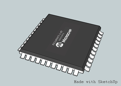
Below is my first try on making a PIC16F887 with TQFP-44 package.
I hope that I will come up with complete 3D designs of my clock projects. It's very fun to do these things.

I have been playing with Eagle3D for sometimes. However, I cannot manipulate my design interactively and cannot export models to render in other 3D renderers. Just today, I found that blueroomelectronics's designs were made with Google SketchUp. So, I downloaded and installed it. The software is very easy to use. But, there is no electronics component library. However, there are some components available for you to download from google 3D warehouse. If you want anything that not available in the google 3D warehouse, you have to make it by yourself.
Below is my first try on making a PIC16F887 with TQFP-44 package.

I hope that I will come up with complete 3D designs of my clock projects. It's very fun to do these things.
Subscribe to:
Posts (Atom)


