Friday, May 21, 2010

DIY LED Watch vs Panerai PAM 127

I have completed a prototype of my LED Watch. I will post the detail about how to make it later. The watch case and strap are missing :)
Features:
- Programmable (via ICSP)
- Vintage 7-segment LEDs with slim sigments
- Powered from a coin cell 3.7V Li-ion rechargeable battery
- Built-in USB battery charger

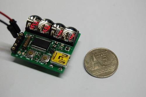
Size comparison between the DIY LED Watch size and a 1 Thai Baht coin.


On my wrist with help of transparent tape :).
DIY Led Watch

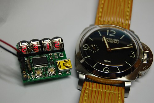
The LED Watch prototype is on the left. Panerai PAM 127 or the "Fiddy" is on the right. In case that you are wondering about the strap, it is custom made from a Louis Vuitton bag.
DIY LED Watch, Panerai PAM127

Please comeback and check out for the making of DIY LED Watch later.

Sunday, January 3, 2010

Eagle negative PCB output for printing

To make a PCB by using Dry Film photo resist, I need the PCB layout in negative mode. However, in Eagle PCB design software, I cannot print the PCB design in negative mode directly. After a few searches, I have found a good way to get negative films of my PCB designs from Eagle PCB software and it is very easy. There are  3 steps.

1. Click ‘CAM’ on the menu bar

cam-select

2. Select ‘PS_INVERTED’ as the output device and then select layers that you want to export

cam-output

3. Click ‘Process Job’ and it’s done!


The output is ‘yourfile.eps’ which is an encapsulated PostScript. You can use Adobe Illustrator or similar Vector based graphics applications to view/edit/print it.

Sunday, November 29, 2009

I'm still alive

Just to let you know that I'm still alive. I'm just too busy (with my child and paid works). However, I have done some microcontroller projects. Yes, they are clock/watch related projects. I also want to complete many projects that the concepts have been proved for example, GPS Clock, Digital Wristwatch etc.,

By the way, I have got many friends via this blog.
Thank you all of you who sending me emails.

Tuesday, August 4, 2009

Small LED dot matrix development board

I was very busy for the past two months so this blog just didn't move. As you may know, the LED dot matrix display is my favorite device. I have designed a small development board for testing my led dot matrix related programs.
The schematic is as the following:
LED dot matrix development board Schematic

The PCB is single sided so I can make it at home. Most of the components are SMD to keep small footprint of the board. The PCB size: 58.4mm x 46mm
LED dot matrix development board PCB

Acutally, I made a PCB and installed all components but the board didn't work :p. It was working when I tested the schematic on breadboard (with through hole version of PIC16F887). I think the SMD PIC16F887 may be broken or the PCB is bad but I just don't have time to figure out the problem. I will try new PCB and PIC16F887.

Sunday, May 17, 2009

USB Coin/Button Cell Battery Charger

I have designed many small footprint PIC projects (such as, pocket watches and wristwatches) but I cannot make them really portable. To make them portable, I need small power sources. Of course, Coin Cell battery would be the smallest DC source that I can buy. The problem is that a Lithium button cell provides 3 V. which is not enough to drive my projects. I thought about using DC-DC step-up converter to boost 3 V. to 5 V. However, it's a little bit complex to add DC-DC converter to the projects. Moreover, my projects consume a lot of power as they consist of many LEDs, a button battery will not last for a day. So, I stopped my think at that point.

Just recently, I have found a rechargeable coin cell battery at Sparkfun.com. It provides 3.7 V. at 200mAh. I don't know that my projects will work at 3.7 V. or not. But, I want to give it a try. For portability, I want to charge the battery from my computer's USB port. So, I designed a USB coin cell battery + charger breakout board. Like many simple battery charger, I use MAX 1555 as the controller of the charger.

The schematic:


The single sided PCB (40mm x 30mm):

The LED goes off when the battery is fully charged (but the charger is still charging).
Please note that the schematic/PCB are just the design and I haven't made it yet. The parts are ordered and I will update when I complete the hardware.