


- Multisim Free Version
- Many types of simulators from Linear Technology
- LTspice IV (Switchercad) is free and powerful. It features all IC chips from Linear Technology. SwitcherCAD™ III is a fully functional Spice III simulator with enhancements and models for easing the simulation of switching regulators. This Spice is a high performance circuit simulator, integrated waveform viewer, which also includes schematic capture. Our enhancements to Spice have made simulating switching regulators extremely fast compared to normal Spice simulators. Included in this download are Spice, Macro Models for 80% of Linear Technology's switching regulators and over 200 op amp models. Furthermore, resistors, transistors and MOSFET models are included as part of this package. With this Spice simulation, viewing of the waveforms of most switching regulators can be achieved in a few minutes on a high performance PC. Also, full circuits using op amps or transistors can easily be simulated.
- Intusoft ICAP4 Demos : A lot of limitations
Monday, October 18, 2010
Free Circuit Simulator Software
My list of Free Circuit Simulator Software
Friday, May 21, 2010
DIY LED Watch vs Panerai PAM 127
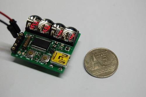
I have completed a prototype of my LED Watch. I will post the detail about how to make it later. The watch case and strap are missing :)
Features:
- Programmable (via ICSP)
- Vintage 7-segment LEDs with slim sigments
- Powered from a coin cell 3.7V Li-ion rechargeable battery
- Built-in USB battery charger
Size comparison between the DIY LED Watch size and a 1 Thai Baht coin.

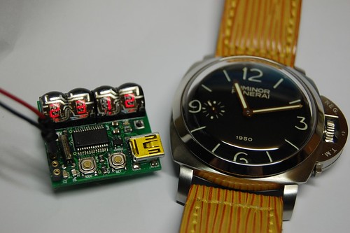
On my wrist with help of transparent tape :).

The LED Watch prototype is on the left. Panerai PAM 127 or the "Fiddy" is on the right. In case that you are wondering about the strap, it is custom made from a Louis Vuitton bag.

Please comeback and check out for the making of DIY LED Watch later.
Features:
- Programmable (via ICSP)
- Vintage 7-segment LEDs with slim sigments
- Powered from a coin cell 3.7V Li-ion rechargeable battery
- Built-in USB battery charger
Size comparison between the DIY LED Watch size and a 1 Thai Baht coin.
On my wrist with help of transparent tape :).

The LED Watch prototype is on the left. Panerai PAM 127 or the "Fiddy" is on the right. In case that you are wondering about the strap, it is custom made from a Louis Vuitton bag.
Please comeback and check out for the making of DIY LED Watch later.
Sunday, January 3, 2010
Eagle negative PCB output for printing
To make a PCB by using Dry Film photo resist, I need the PCB layout in negative mode. However, in Eagle PCB design software, I cannot print the PCB design in negative mode directly. After a few searches, I have found a good way to get negative films of my PCB designs from Eagle PCB software and it is very easy. There are 3 steps.
1. Click ‘CAM’ on the menu bar

2. Select ‘PS_INVERTED’ as the output device and then select layers that you want to export

3. Click ‘Process Job’ and it’s done!
The output is ‘yourfile.eps’ which is an encapsulated PostScript. You can use Adobe Illustrator or similar Vector based graphics applications to view/edit/print it.
Sunday, November 29, 2009
I'm still alive
Just to let you know that I'm still alive. I'm just too busy (with my child and paid works). However, I have done some microcontroller projects. Yes, they are clock/watch related projects. I also want to complete many projects that the concepts have been proved for example, GPS Clock, Digital Wristwatch etc.,
By the way, I have got many friends via this blog.
Thank you all of you who sending me emails.
By the way, I have got many friends via this blog.
Thank you all of you who sending me emails.
Tuesday, August 4, 2009
Small LED dot matrix development board
I was very busy for the past two months so this blog just didn't move. As you may know, the LED dot matrix display is my favorite device. I have designed a small development board for testing my led dot matrix related programs.
The schematic is as the following:

The PCB is single sided so I can make it at home. Most of the components are SMD to keep small footprint of the board. The PCB size: 58.4mm x 46mm

Acutally, I made a PCB and installed all components but the board didn't work :p. It was working when I tested the schematic on breadboard (with through hole version of PIC16F887). I think the SMD PIC16F887 may be broken or the PCB is bad but I just don't have time to figure out the problem. I will try new PCB and PIC16F887.
Subscribe to:
Posts (Atom)


