


Just to let you know that I'm still alive. I'm just too busy (with my child and paid works). However, I have done some microcontroller projects. Yes, they are clock/watch related projects. I also want to complete many projects that the concepts have been proved for example, GPS Clock, Digital Wristwatch etc.,
By the way, I have got many friends via this blog.
Thank you all of you who sending me emails.
Sunday, November 29, 2009
Tuesday, August 4, 2009
Small LED dot matrix development board
I was very busy for the past two months so this blog just didn't move. As you may know, the LED dot matrix display is my favorite device. I have designed a small development board for testing my led dot matrix related programs.
The schematic is as the following:

The PCB is single sided so I can make it at home. Most of the components are SMD to keep small footprint of the board. The PCB size: 58.4mm x 46mm

Acutally, I made a PCB and installed all components but the board didn't work :p. It was working when I tested the schematic on breadboard (with through hole version of PIC16F887). I think the SMD PIC16F887 may be broken or the PCB is bad but I just don't have time to figure out the problem. I will try new PCB and PIC16F887.
Sunday, May 17, 2009
USB Coin/Button Cell Battery Charger
I have designed many small footprint PIC projects (such as, pocket watches and wristwatches) but I cannot make them really portable. To make them portable, I need small power sources. Of course, Coin Cell battery would be the smallest DC source that I can buy. The problem is that a Lithium button cell provides 3 V. which is not enough to drive my projects. I thought about using DC-DC step-up converter to boost 3 V. to 5 V. However, it's a little bit complex to add DC-DC converter to the projects. Moreover, my projects consume a lot of power as they consist of many LEDs, a button battery will not last for a day. So, I stopped my think at that point.
Just recently, I have found a rechargeable coin cell battery at Sparkfun.com. It provides 3.7 V. at 200mAh. I don't know that my projects will work at 3.7 V. or not. But, I want to give it a try. For portability, I want to charge the battery from my computer's USB port. So, I designed a USB coin cell battery + charger breakout board. Like many simple battery charger, I use MAX 1555 as the controller of the charger.
The schematic:

The single sided PCB (40mm x 30mm):

The LED goes off when the battery is fully charged (but the charger is still charging).
Please note that the schematic/PCB are just the design and I haven't made it yet. The parts are ordered and I will update when I complete the hardware.
Tuesday, April 14, 2009
Classic LED 7-Segment Displays
Just recently I have been addicted to old LED displays as they are small and bright and I love the classic look. We can see them in vintage calculators and vintage led watches. However these displays consume significant amount of power, so they are not used in watches and calculators anymore. As they are replaced by LCD, these LED 7-Segment displays are not in production anymore and difficult to obtain.
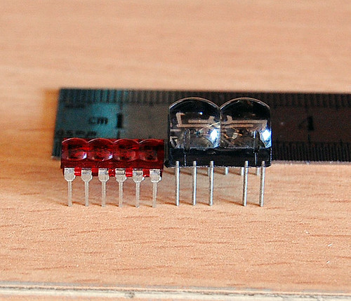
Now, I have 2 models of the classic LED 7-Segment as shown in the picture below: HP 5082-7414 from HP is on the left. It’s a 4-digit Red LED 7-Segment very nice for wristwatch. The one on the right is an 2-digit Red LED 7-Segment from an unknown maker. It can be used in a wristwatch too (with a little bit bigger case).
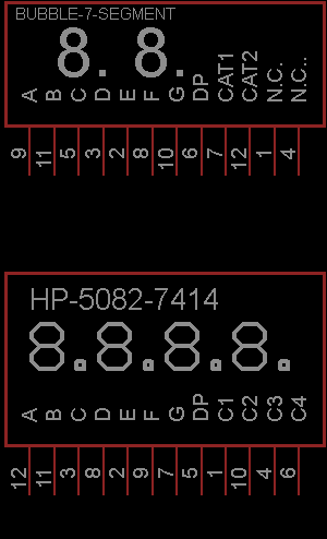
Based on my inspection, I have made symbols for these displays with Eagle 5.4.0 free version. The displays are common cathode and the symbols are below
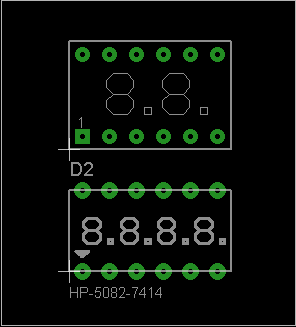
The PCB footprints are as the following (DIP 12)
I have made simple clocks using these displays and PIC16F887. The real thing looks much better than the photo. The displays are bright red and sun light viewable. Very COOL!!! They are on my computer desk and I love to see them very often.

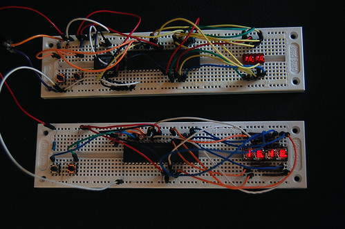
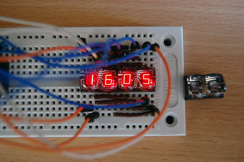
Each clock consumes about 0.25W (50mA, 5V) when the PIC16F887 operates at 250kHz (display refresh rate is about 61Hz). The amount of consumed current can be reduced significantly if I use some current limit resistors. But the displays will be dimmer than without resistors. I will try to use PWM for reducing the power consumption as I don’t want to put 8 resistors into my design. The schematic/PCB and firmware including source code in MikroC will be made public once I have complete all of the designs. I will even have kits for sell if my time permitted.
Now, I have 2 models of the classic LED 7-Segment as shown in the picture below: HP 5082-7414 from HP is on the left. It’s a 4-digit Red LED 7-Segment very nice for wristwatch. The one on the right is an 2-digit Red LED 7-Segment from an unknown maker. It can be used in a wristwatch too (with a little bit bigger case).
Based on my inspection, I have made symbols for these displays with Eagle 5.4.0 free version. The displays are common cathode and the symbols are below
The PCB footprints are as the following (DIP 12)
I have made simple clocks using these displays and PIC16F887. The real thing looks much better than the photo. The displays are bright red and sun light viewable. Very COOL!!! They are on my computer desk and I love to see them very often.
Each clock consumes about 0.25W (50mA, 5V) when the PIC16F887 operates at 250kHz (display refresh rate is about 61Hz). The amount of consumed current can be reduced significantly if I use some current limit resistors. But the displays will be dimmer than without resistors. I will try to use PWM for reducing the power consumption as I don’t want to put 8 resistors into my design. The schematic/PCB and firmware including source code in MikroC will be made public once I have complete all of the designs. I will even have kits for sell if my time permitted.
Wednesday, March 11, 2009
Setting Internal Oscillator for PIC16F627A
I love to use PIC16F627A and PIC16F628 because they come with internal oscillators. That means I can make a project with lower component count (without 1 crystal and 2 load capacitors). The project setting of MikroC for using internal oscillator of the PIC16F627A shows below:


Subscribe to:
Posts (Atom)


