Tuesday, April 14, 2009

Classic LED 7-Segment Displays

Just recently I have been addicted to old LED displays as they are small and bright and I love the classic look. We can see them in vintage calculators and vintage led watches. However these displays consume significant amount of power, so they are not used in watches and calculators anymore. As they are replaced by LCD, these LED 7-Segment displays are not in production anymore and difficult to obtain.

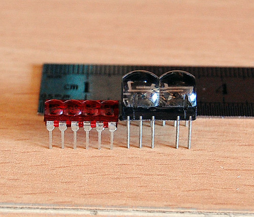
Now, I have 2 models of the classic LED 7-Segment as shown in the picture below: HP 5082-7414 from HP is on the left. It’s a 4-digit Red LED 7-Segment very nice for wristwatch. The one on the right is an 2-digit Red LED 7-Segment from an unknown maker. It can be used in a wristwatch too (with a little bit bigger case).

LED 7-Segment Display HP 5082-7414

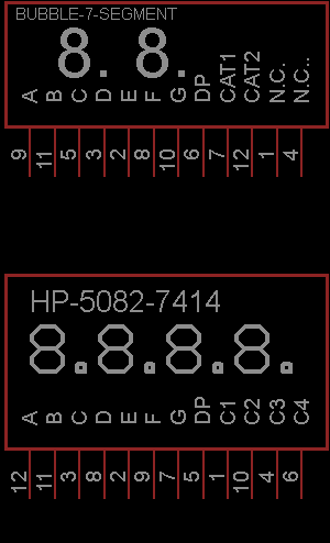
Based on my inspection, I have made symbols for these displays with Eagle 5.4.0 free version. The displays are common cathode and the symbols are below

LED 7-Segment Display HP 5082-7414 schematic

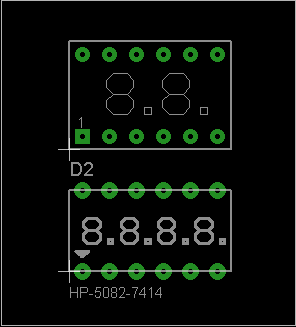
The PCB footprints are as the following (DIP 12)

LED 7-Segment Display HP 5082-7414 PCB footprint

I have made simple clocks using these displays and PIC16F887. The real thing looks much better than the photo. The displays are bright red and sun light viewable. Very COOL!!! They are on my computer desk and I love to see them very often.
bubble-7-segment-clock

LED 7-Segment Display HP 5082-7414 clock

LED 7-Segment Display HP 5082-7414 digital clock

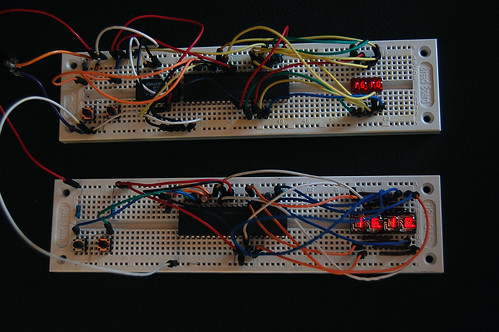
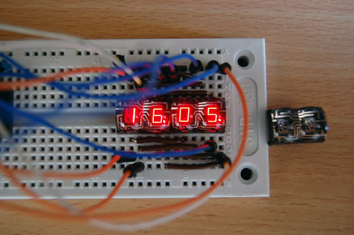
Each clock consumes about 0.25W (50mA, 5V) when the PIC16F887 operates at 250kHz (display refresh rate is about 61Hz). The amount of consumed current can be reduced significantly if I use some current limit resistors. But the displays will be dimmer than without resistors. I will try to use PWM for reducing the power consumption as I don’t want to put 8 resistors into my design. The schematic/PCB and firmware including source code in MikroC will be made public once I have complete all of the designs. I will even have kits for sell if my time permitted.

Wednesday, March 11, 2009

Setting Internal Oscillator for PIC16F627A

I love to use PIC16F627A and PIC16F628 because they come with internal oscillators. That means I can make a project with lower component count (without 1 crystal and 2 load capacitors). The project setting of MikroC for using internal oscillator of the PIC16F627A shows below:
Setting MikroC for Internal Oscillator

Saturday, March 7, 2009

Multisim Analog Devices Edition 10.0 Free Download

I have found a good and free circuit simulator,Multisim Analog Devices Edition 10.0. As you may know that Multisim is a famous electronics circuit simulation software (circuit simulator). It's based on Electronics Workbench from the same company. I have found the free version (not the cracked version) of Multisim by chance and you may not find it on the National Instruments website. It comes with a lot of measurement tools and it's very easy to use. I use it to simulate various analog circuits. The image below shows the screen shot of the simulation of DC-Boost Converter (12V to 150V step up).
Multisim Analog Devices Edition 10.0

Not only analog circuit, but it also simulates digital circuit as one may call it 'Mixed-Mode Simulator'.
Some features and limitations:
  • Build simulated component evaluation circuits to quickly assess behavior of over 800 Analog Devices operational amplifiers, switches and voltage references
  • Examine the unit under test in the intended circuit topology with up to 25 components
  • Use built-in instruments and analyses including oscilloscopes and worst-case analysis
  • Swap components easily to pinpoint best design options
  • Link to the Analog Devices Design Center for more online evaluation tools
  • Instantly access product pages and datasheets of each Analog Devices component
  • Upgrade to a full edition of NI Multisim to complete designs and transfer to board layout with NI Ultiboard

Please follow the link for Free Download Multisim 183MB

Friday, February 20, 2009

1Hz Clock Generator using PIC12F675

Based on the idea from http://www.josepino.com/pic_projects/?timebaseI have created a 1Hz Clock Generator. I use PIC12F675 as it's available locally. Its price is just about US$1.
The concept is using 32.768kHz crystal as a clock for the PIC. Therefor, the internal instruction clock is 32768/4 = 8192 Hz. By using the 16 bit Timer1 to count the instruction clock cycles, the interrupt will occur every 8 second. This period can be reduced by setting initial value of the Timer1 (TMR1H:TMR1L). I have to make Timer1 to count up to 8192 for generating overflow interrupt every 1 second. To make Timer1 count up to 8192, the initial value of TMR1 must be 65536-8192 = 57344 or 0xE000. This means TMR1H = 0xE0 and TMR1L = 0x00. In this case, I need to set only the TMR1H=0xE0 and let TMR1L runs continuously. By changing the initial value of Timer1, I can generate almost any frequencies.

An application for this project is a precise 1Hz blinking LED signal :) ha ha. I know that it's not useful but I think it's fun to look at (am I crazy?). Another application is a precise 1Hz time base for a clock.

The source code is written in MikroC.

// PIC12F675
// 1Hz Time Base Osc.
// Timer1 Module
// 32.768 KHz
unsigned short tick;
void Init ();
void interrupt ()
{
        if (PIR1.TMR1IF)
        {
                TMR1H = 0xE0;
                PIR1.TMR1IF = 0;
                tick = 1;
        }
}
void main ()
{
        tick = 0;
        //Initialize Ports and Timer1 Module
        Init ();
        while (1)
        {
                if (tick)
                {
                        tick = 0;
                        GPIO = (1 << 2);
                }
                if (TMR1H > 0xF0)
                {
                        GPIO = 0;
                }
        }
}
void Init ()
{
        TRISIO = 0;
        //Make all pins as output ports
        GPIO = 0;
        //Use Timer1 module
        INTCON.GIE = 1;
        INTCON.PEIE = 1;
        T1CON = 0x01;
        //Overflow every 8192
        TMR1H = 0xE0;
        TMR1L = 0x00;
        //  Enable TMR1 interrupt
        PIE1.TMR1IE = 1;
}


The schematic is as the following image.
1Hz Clock generator using PIC12F675


The PCB:


3D version:

Wednesday, February 11, 2009

Transistor array

I am looking for transistor arrays for my LED projects as I want to reduce number of components on board. After some searches, I have found that there are two candidates for current source and sink transistor arrays as the following:
UDN2981 : 8 channels high current source MAX 500mA
UDN2981 : 8 channels high current source
ULN2003 : 7 channels high current sink MAX 500mA

ULN2003 : 7 channels high current sink
I will use these transistor arrays for driving large 7-segment display panel , bright led dot matrix panel and other LED projects.