Saturday, November 22, 2008

Small Nixie Tube

I have a plan to build a Nixie Clock so I search for its information and blog it here for further reference.

IN-16 may be not the smallest nixie tube but it's small enough to make a nice desk top nixie clock. The character height is about 13mm. I will use IN-16 for my upcoming nixie clock. There are some nixie clock kits that use IN-16 nixie tube so I am thinking about buying a kit or building it from scratch.

The cheapest PIC with Internal Osc and I2C


I just got the above FM receiver module from SparkFun. It requires I2C interface. Actually, I2C can be implemented in software but I need I2C hardware so I can do something else in software. So, I went to microchip.com and searched for the cheapest PIC Microcontroller that comes with internal oscillator and I2C. Based on my search, PIC16F722 is the cheapest PIC with 16MHz internal osc. and I2C interface. Its price is $0.91 for 1000 pcs. I also found that PIC16F505 is the cheapest PIC that comes with internal oscillator (4MHz, $0.56/1000pcs.).

Anyway, I will develop my FM radio with PIC16F887 as I have it in hand.

Wednesday, November 19, 2008

PCB for 7-Segment PIC Digital Clock

I have designed a single-sided PCB for the PIC Digital Clock. Because the autorouter is not good for routing single-sided PCB so I have to route by hand. It was my first hand routed PCB design and it was a time consuming task. I haven't tested the PCB yet. Use it by your own risk. I will produce this PCB and test it later.

As I don't have server to upload the Eagle file, please contact me if you want the file or PDF version of the image below.

PCB for 7-Segment PIC Digital Clock

Components side of the PCB. The red lines are jumpers.
Component placement on the PCB of 7-Segment PIC Digital Clock

Sunday, November 16, 2008

7-Segment PIC Digital Clock : The photographs

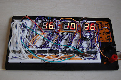
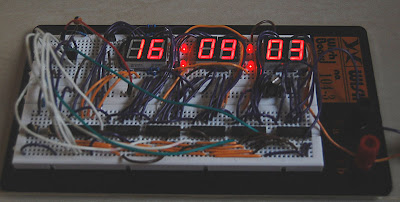
The prototype of the 7-Segment PIC Digital Clock. Check out 7-Segment Digital Clock for the schematic and source code.
7-Segment Digital Clock
7-Segment Digital Clock PIC Microcontroller
7-Segment Digital Clock PIC16F627A
7-Segment Digital Clock PIC16F628

Saturday, November 15, 2008

Using 11.2896 MHz with TMR1 (timer1 module)

11.2896 MHz Rubidium Frequency Standard

A precision clock is my ultimate goal of making clocks. I know that cesium oscillator is to most precise clock on earth. However, a cesium clock is too expensive to play with. My option is using Rubidium oscillator which is the second most accurate oscillator after the cesium (I don't have reference about this) and its cost is more accessible. Searching on eBay about Rubidium Frequency Oscillator brought me to Ultra low jitter 11.2896Mhz Rubidium Frequency Clock . I am thinking about buying this item.
The question is 'How to make use of 11.2896 MHz frequency oscillator with my clock?'. If I run my MCU with this frequency, the internal frequency will be 11.2896MHz/4 = 2.8224 MHz. How to use this frequency to drive timer1 module for making a precision clock? TMR1 is a 16bit timer so it can count from 0 to 65535 before overflow. If I use TMR1 with this frequency without any setting, the TMR1 will send interrupt 2822400/65536= 43.06640625Hz or every 0.023219955 second which is unusable.
I have to find the initial value of the TMR1 for the best precision . The conditions are
1. The number of interrupts per second must be integer so I can count it precis
2. The initial value must be in form 0x##00. That means I have to set only the first 2 bits of TMR1 (TMR1H) as setting the lower bits takes some time and effects the clock precision.

The Solution
Expanding 2822400 results
2822400 = 256 x 49 x 25 x 9 = 57600 x 49
The meaning
If I set TMR1 to count upto 57600, it will send interrupt 49 times/second. Wow! It meets my first condition. To set TMR1 to count up to 57600, I have to set the initial value of TMR1 to 65536-57600 = 7936 = 0x1F00. Wow again!! It meets the second condition.

Now, I have to set TMR1H = 0x1F and count the number of interrupts to 49 to get 1 second time interval. Just perfect!